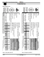
Section 4-2-1: Venting Layout
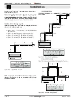
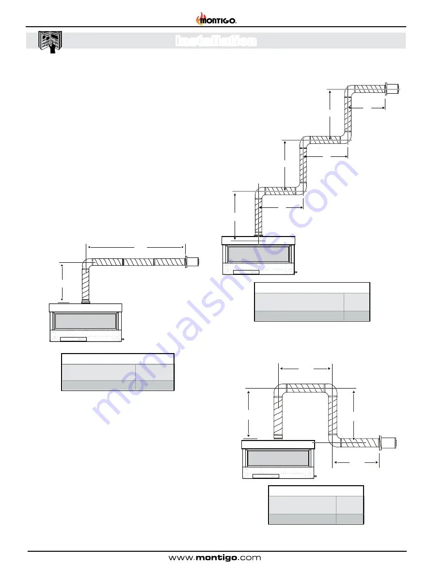
Selection of components and details of venting lay out should
adheretothefollowingguidelines
:
■ Ensure there is a minimum run of 2’ of straight pipe before
the power vent.
■ Ensure the maximum vent run does not exceed 100’.
■ Ensure the number of 90° elbows does not exceed 6.
■ Ensure the number of 45° elbows does not exceed 12.
Figure 4 Sec.4. Typical Venting Installations.
Multi-Elbow Installations
Multi-elbow installations are possible up to a maximum of six
at 90° elbows.
Figure 5 Sec.4
. Multi-elbow Venting Installations.
Figure 6 Sec.4
Downward Venting Installations.
Downward Vertical Venting
Note: The downward vent run must not exceed 6' of vent run.
Section 4-2: Installing a Wall Mounted Horizontal
ExteriorPowerVent
Thissectionappliestoinstallationswheretheshortestpossible
vent run is through an exterior wall
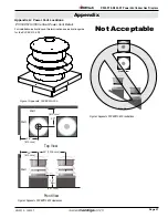
. Refer to
AppendixA -
PowerVentlocations
, to ensure the planned Power vent location
is acceptable. Once the vent location has been established, please
refer to the appropriate section below for installation details.
Venting Installation
V+H(MaximumLength)
Max.#
Elbows
100 Feet
six 90
MultiElbow-VentingInstallation
V1 + H1 + V2 + H2 + V3 = H3
(MaximumLength)
Max.#
Elbows
100 Feet
6
MultiElbow-VentingInstallation
V1 + H1 + D + H2
(MaximumLength)
Max.#
Elbows
40 Feet
6
H
V
Elbow 1
Elbow 2
Elbow 3
Elbow 5
Elbow 4
Elbow 6
H3
H2
H1
V1
V2
V3
H2
H1
V
D
Note:
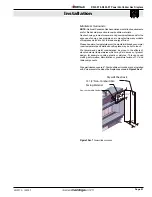
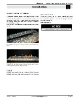
Images are shown without screens for clarity purposes.
However, your fireplace should not be operated without proper
installation of screens.
R520-ST & R620-ST Power Vent Indoor Gas Fireplace
Page 14
XG0773 - 150127
Installation


