RP620 Power Vent Indoor Gas Fireplace
Page 28
XG0777 - 100113.1
Installation
Section 7:Testing the System
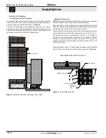
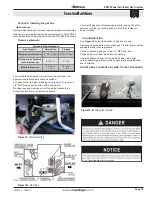
Connect two 1/8" MPT hose barb fittings to the gas valve inlet
and outlet ports, as shown in
figure 14
. Connect a 0-16" W.C.
manometer to each fitting.
Turn on the gas supply to the appliance.
Wait 3 minutes and check for any gas leaks. If you smell or
detect a gas leak, turn the gas supply off and take corrective actions.
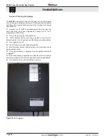
Turn supply power on.
The LED power indicator will be illuminated.
Install the inner window, light tray glass, and outer window (see
appropriate sections).
Place the appliance in operation See the lighting instructions
on
page 37
.
Once the appliance is operational, confirm the manifold pressure
and supply pressure are within the specified limits, see
section 5
.
Turn lights on and confirm all lights are working.
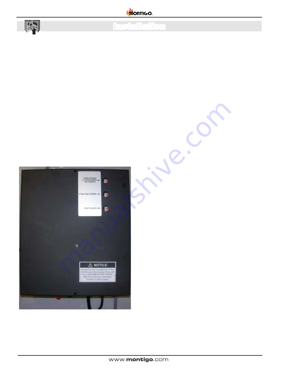
The
RP620*
Control and Power Vent System can be safely tested
prior to finishing the fireplace enclosure. This test can be done quickly
and efficiently to ensure all systems function according to the design
specifications.
Figure 19.
LED Indicators

