RP620 Power Vent Indoor Gas Fireplace
Page 33
XG0777 - 100113.1
Installation
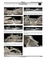
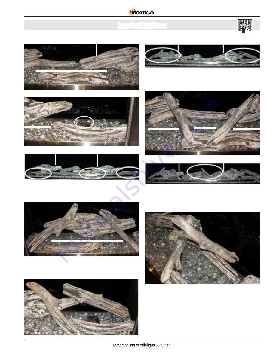
Figure 24h.
3
Ports
Figure 24i.
Pilot
Ports
3
Figure 24j.
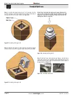
Step 3: From LGS58, place log 4 on the left side of the left log from
LGS57. Cross log 4 over the ports. Place log 5 on the right side of
the left log from LGS57. Cross log 5 over the ports. See figure 24k.
Figure 24k.
4
5
Ports
From LGS58, Place log 4 on the right log from LGS57. Cross log
4 over the ports. Place log 2 on the right end of the right log from
LGS57, See Figure 24l.
Figure 24L.
4
2
Step 5: From LGS58, Place log 5 on top of the end of the right log from
LGS57 and cross the burner to log 3, see figure 24m. Place log 6 on
top of the end of log 2 and cross the burner to log 3 see figure 24n.
Figure 24m.
5
6
3
Ports
Figure 24.n
Figure 24o.
Step 6: Place log 6 from LGS58 on top of log 1 near the middle of
the burner. Cross log 6 on top p of the first log 6 installed in step 5.
See figure 24p.
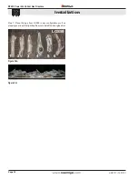
Figure 24p.

