RP620 Power Vent Indoor Gas Fireplace
Page 46
XG0777 - 100113.1
Installation
Inset
Step 2:
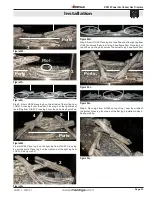
Install the Vent pipe female end up 2" to 3" maximum from the
top of the chase box. Install the electrical harness (EPVH-10-100) that will
communicate with the Power Vent module, see
Figure 13a.
Figure 13b.
.Installing.the.Rough-in.Kit..
Step 3:
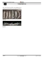
Install the Vent rough-in kit. Pull wire harness through the supplied
hole in the bottom corner of the rough-in box and snap into the slot provided.
Figure 13b.
.Installing.the.Rough-in.Kit..
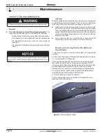
Step 4: Place the termination head over chase and fasten with 4
screws on the vertical sides of the base plate. Silicone or seal the
base plate in any location necessary to keep the structure of the
building free of water or moisture.
Figure 13b.
.Installing.the.Rough-in.Kit..
Step 5:
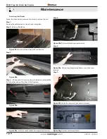
Install the Power Vent module power harness. Hold the Power
Vent in close proximity to the assembled chase. With stainless steel cover
attached, plug in the power harness. Note the direction and orientation of
the plug socket, see
Figure 13e.
Electrical Harness
from Power Vent
Figure 13e.
.
Installed power harness.


