background image

DEFROSTING

A) FRIDGE COMPARTMENT

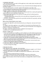
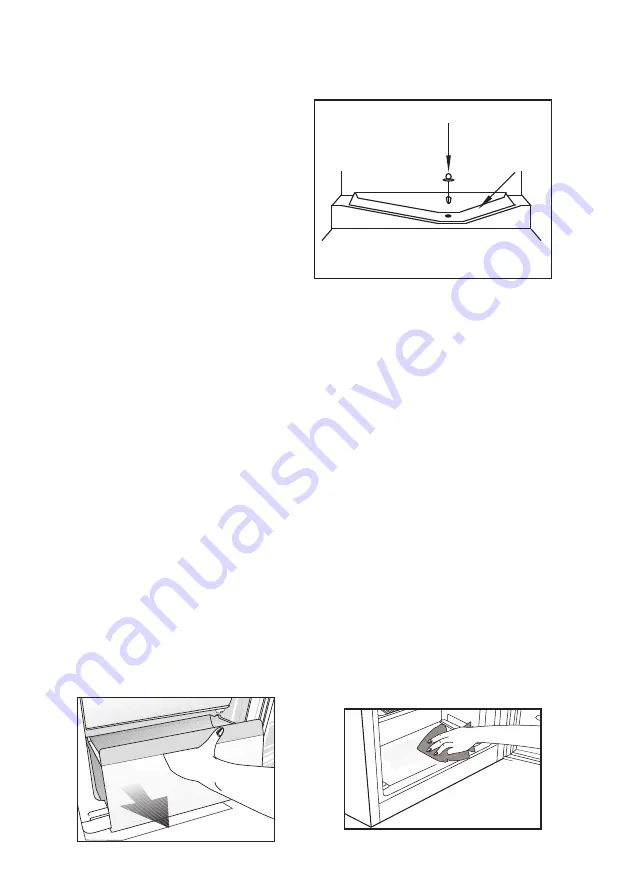
The fridge compartment defrosts

automatically. The defrosting water runs

to the drain tube via a collection

container at the back of the appliance (1).

(see diagram)

1

2

(1)

(2)

During defrosting water droplets may form

at the back of the fridge compartment

where concealed evaporator is located.

Some droplets may remain on the liner and

refreeze when defrosting is completed. Do

not use pointed or sharp edged objects such as knives, forks to remove the droplets


which have frozen.

If at any time the defrosted water does not drain from the collection channel, check


to ensure that no food particles have blocked the drain tube. The drain tube can


be 

cleared by pushing the special plastic plunger provided down the drain tube

(2). If the frost layer reaches about 1/4"(7 mm), reduce the setting (i.e. from 4 to 1) to 

restart automatic defrosting.

B) FREEZER COMPARTMENT

Deep freezer compartment does not perform automatic defrosting in order to

prevent decaying of the frozen food.

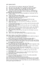
Defrosting is very straightforward and without mess, thanks to a special defrost 

collection basin. Defrost twice a year or when a frost layer of around 7 (1/4”) mm


has formed. 

To start the defrosting procedure, switch off the appliance at the socket outlet and 

pull out the mains plug.

All food should be wrapped in several layers of newspaper and stored in a cool 

place (e.g. fridge or larder). 

Remove all freezer drawers. 

Containers of warm water 

may be placed carefully in the freezer to speed up the defrosting.

Do not use pointed or sharp-edged objects, such as knives or forks to remove the 

frost. Never use hair dryers, electrical heaters or other such electrical appliances for 

defrosting. Sponge out the defrost water collected in the bottom of the freezer 

compartment. After defrosting, dry the interior thoroughly.

Insert the plug into the wall socket and switch on the electricity supply.

Drain Tube

Defrosted

Water

Collection

Summary of Contents for MIFF501

Page 1: ...uctions carefully before attempting to install or use this appliance We recommend that you keep these instructions in a safe place for future reference Installation and Operating Instructions THE PERF...

Page 2: ...ith your Fridge you can rest assured that you are fully protected against the cost of repairs for the first 5 Years Please note that any claim must be accompanied by the model reference number serial...

Page 3: ...e best possible performance and trouble free operation from your appliance it is very important to carefully read these instructions Ensure that the plug remains readily accessible Do not use multiple...

Page 4: ...ERATURE CONTROL AND ADJUSTMENT STARTING STORING FROZEN FOOD FREEZING FRESH FOOD MAKING ICE CUBES DEFROSTING CLEANING AND CARE REPLACING THE INTERIOR LIGHT BULB DO S AND DON TS ENERGY SAVING TIPS PROBL...

Page 5: ...ifying the terminals in your plug proceed as follows FITTED WITH BS 1362 13A FUSE ALWAYS FIT BS 1362 REPLACEMENT CARTRIDGE FUSE GREEN YELLOW OR GREEN N BLUE OR BLACK L BROWN OR RED 22mm 6mm 6mm 6mm 32...

Page 6: ...parts and doors pipes wall coverings etc Do not move the appliance by pulling by the door 6 7 Empty any water in the drain tray before moving See section Defrosting and Care cleaning forfurtherinforma...

Page 7: ...put your fridge freezer in a cold room where the temperature is likely to go below 10 degrees C 50 degrees F during night time and or especially in winter If the ambient temperature is below 0 degree...

Page 8: ...D STORAGE DRAWERS CABINET SHELVES TEMPERATURE SETTING KNOB INTERIOR LIGHT BOTTLE SHELF DOOR SHELF DOOR SHELF SALAD CRISPER C Figures in this user manual are schematic and may not match the product exa...

Page 9: ...hot food and beverages to cool before placing them in the fridge Do not store explosive substances High proof alcohol must be stored upright in sealed containers Left over canned food should not be s...

Page 10: ...ecommend that you check the temperature with an accurate thermometer to ensure that the storage compartments are kept to the desired temperature Remember you must take your reading very quickly since...

Page 11: ...e compressor is running or not which is quite normal 5 Set temperature setting knob half way between 1 and 5 6 Front edges of the cabinet may feel warm This is normal These areas are designed to be wa...

Page 12: ...ng B FREEZER COMPARTMENT Deep freezer compartment does not perform automatic defrosting in order to prevent decaying of the frozen food Defrosting is very straightforward and without mess thanks to a...

Page 13: ...e have to withstand extreme physical conditions such as temperatures below 20 C ENERGY SAVING TIPS 1 Ensure your appliance is installed in a well ventilated area If the ambient temperature is low but...

Page 14: ...ve ice cream from the freezer 10 20 minutes before serving Don t Store bananas in your fridge compartment Don t Store melon in your fridge It can be chilled for short periods as long as it is wrapped...

Page 15: ...n Taking help from someone to slightly lift the refrigerator will facilitate this process If the subject parts are not included in the product you have purchased then it is valid for other models The...

Page 16: ...16 775 40 71 855 1778 1788...

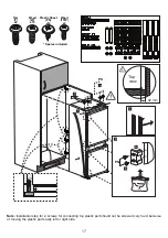
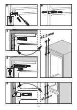
Page 17: ...or connecting top plastic part should not be screwed very hard because of moving the plastic part easily left or right side 90o 2 1 3 5 1 a 4 b PS PS 17 Torx T x6 Wood W x15 Plastic Sheet PS x12 Wood...

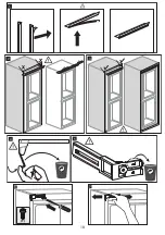
Page 18: ...18 1 2 3 4 5 6 T 7...

Page 19: ...19 8 10 9 11 T 42 0 mm 42 0mm 1TW 12 42 0 mm 42 0mm...

Page 20: ...20 14 13 T 1TW 15 17 16 1TW 42 0 mm 42 0mm W 2 0 mm 18...

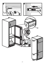
Page 21: ...21 20 19 22 90 o 21 mm W 21 W 2 mm 2 mm 2 mm...

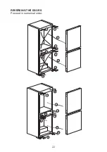
Page 22: ...22 REVERSING THE DOORS Proceed in numerical order 1 2 7 3 4 5 6 10 8 9 19 20 18 21 15 17 14 13 16 12...

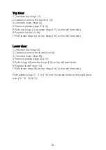
Page 23: ...it lower hinge 3 as top hinge 19 on the left hand side Lower door 1 Unscrew top hinge 4 2 Carefully remove the lower door 5 3 Unscrew lower hinge 6 4 Remove plastic plugs 9 10 5 Refit hinge 4 as lower...

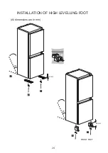
Page 24: ...All dimensions are in mm 1 3 3 2 2 45 FRONT FEET 45 8 mm 59 mm INSTALLATION OF HIGH LEVELLING FOOT 24...

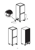
Page 25: ...25 4 5 REAR FEET 45...

Page 26: ...555 26 1836 855 32 71 540 545 91 775 1836 855...

Page 27: ...horised modification or inexpert repair Cost of Call out where a fault cannot be found with the appliance Cost of Call out for work covering routine maintenance such as but not exclusively cleaning of...

Page 28: ...l help prevent potential negative consequences for the environment and human health which could otherwise be caused by inappropriate waste handling of this product For more detailed information about...

Reviews: