background image

PB24

Energía De Entrada: 110 Consumo De Energía de VAC/220VAC 

1A/.5A: 1Amp (120 vatios) en 120 VAC de salida de energía: VA 

96 en 24 VAC 52 vatios de Heater/Blower 32 vatios de energía de 

la cámara fotográfica

Todo el interruptor principal del poste con un contacto de por lo 

menos 3m m en cada poste será incorporado en la instalación 

eléctrica del edificio.

Herramientas Requeridas: destornillador de cabeza llana del 

150"7/16 llave de la llave o del zócalo 9/16 o zócalo

Puissance D'entrée : 110 Puissance D'Énergie de VAC/220VAC 

1A/.5A : 1Amp (120 watts) à 120 VCA de rendement de 

puissance : VA 96 à 24 VCA 52 watts de Heater/Blower 32 watts 

de puissance d'appareil-photo

Un tout le commutateur principal de poteau avec un contact au 

moins de 3mm dans chaque poteau sera incorporé dans 

l'installation électrique du bâtiment.

Outils Requis : tournevis à tête plate de 150"7/16 clé de clé ou de 

douille 9/16 ou douille

Zugeführte Energie: 110 VAC/220VAC 1A/.5A Leistungsaufnahme: 

1Amp (120 Watt) bei 120 VAC Abgabeleistung: VA 96 bei 24 VAC 

52 Watt Heater/Blower 32 Watt Kamera-Energie

Ein aller Pfostenhauptschalter mit einem Kontakt von 3mm 

mindestens in jedem Pfosten wird in der elektrischen Installation 

des Gebäudes enthalten.

Werkzeuge Erforderten: 150"Flachkopfschraubenzieher 7/16 

Schlüssel-oder Einfaßung 9/16 Schlüssel oder Einfaßung

Poder De Entrada: 110 Consumo De Potência de VAC/220VAC 

1A/.5A: 1Amp (120 watts) em 120 VAC de saída de poder: VA 96 

em 24 VAC 52 watts de Heater/Blower 32 watts de poder da 

câmera

Todo o interruptor principal do pólo com um contato ao menos 

de 3mm em cada pólo será incorporado na instalação elétrica 

do edifício.

As Ferramentas Requereram: chave de fenda flathead do 

150"7/16 de chave da chave ou do soquete 9/16 ou soquete

Alimentazione in ingresso Di Entrata: 110 Assorbimento di corrente 

Di energia di VAC/220VAC 1A/.5A: 1Amp (120 watt) a 120 VCA di 

uscita di alimentazione: VA 96 a 24 VCA 52 watt di Heater/Blower 

32 watt di alimentazione della macchina fotografica

Tutto l'interruttore principale del palo con un contatto almeno di 

3mm in ogni palo sarà compreso nell'installazione elettrica della 

costruzione.

Attrezzi Richiesti: cacciavite a testa piatta del 150"7/16 di chiave 

dallo zoccolo o dalla chiave 9/16 o zoccolo

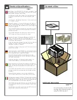
Input Power: 110 VAC/220VAC 1A/.5A Power Consumption: 1Amp 

(120 Watts) at 120 VAC Power Output: 96 VA at 24 VAC 52 Watts 

Heater/Blower 32 Watts Camera Power

An all pole main switch with a contact of at least 3mm in each 

pole shall be incorporated in the electrical installation of the 

building.

Tools Required: .150” Flathead Screwdriver 7/16 Wrench or Socket
 9/16 Wrench or Socke

Electrical Specifications

Français

Deutsch

Italiano

Portuguese

Español

English

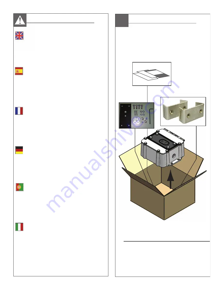
Contents of Box

Additional Information:

NOTE ****

Power Supplies provided with 

housing will not be required if

using the PB24 product.

Summary of Contents for PB24RS

Page 1: ...P Reset Installation Steps 1 Check the package contents 2 Select Operation Mode 3 Install Hardware a Timed Reset Mode b Intelligent Reset Mode 4 Read LED Operation instructions 5 Install Software www videolarm com Technical Support Setup Tools IP Reset Installation Software Before attempting to connect or operate this product please read these instructions completely 81 IN5419 12 22 2011 2011 Moog...

Page 2: ...n be damaged if improperly handled or dropped If an item appears to have been damaged in shipment replace it properly in its carton and notify the shipper Be sure to save 1 The shipping carton and packaging material They are the safest material in which to make future shipments of the equipment 2 These Installation and Operating Instructions If technical support or service is needed contact us at ...

Page 3: ...spect to any Product requiring service during the warranty period which is subjected to any of the following abuse improper use negligence accident lightning damage or other acts of God i e hurricanes earthquakes modification failure of the end user to follow the directions outlined in the product instructions failure of the end user to follow the maintenance procedures recommended by the Internat...

Page 4: ...der Einfaßung Poder De Entrada 110 Consumo De Potência de VAC 220VAC 1A 5A 1Amp 120 watts em 120 VAC de saída de poder VA 96 em 24 VAC 52 watts de Heater Blower 32 watts de poder da câmera Todo o interruptor principal do pólo com um contato ao menos de 3mm em cada pólo será incorporado na instalação elétrica do edifício As Ferramentas Requereram chave de fenda flathead do 150 7 16 de chave da chav...

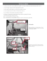
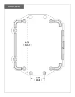
Page 5: ...l mount bracket must be attached using the gasket as shown El soporte del montaje de la pared se debe unir usando la junta según lo demostrado La parenthèse de bâti de mur doit être jointe utilisant la garniture comme montrée Der Wandeinfassung Haltewinkel muß mit der Dich tung angebracht werden wie gezeigt worden O suporte da montagem da parede deve ser unido usando a gaxeta como mostrado La staf...

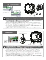
Page 6: ...OUTPUT 24VAC HEATERS CAMERA Internal resettable fuses are supplied for the main 24VAC output lines Do not connect heaters to camera output The PB24 is not designed for 3 phase or 208V systems Los fusibles restaurables internos se proveen para las líneas de salida principales 24VAC No conecte los calentadores con la salida de la cámara fotográfica El PB24 no se diseña para 3 fases o sistemas 208V D...

Page 7: ...e loss of the relay toggle after a predetermined detection period it power restarts the protected device Generally a power reset will restore the device to proper operation After 2 failed attempts to restore the device s operation IP Reset will re start the protected device once every four hours fault detection mode Timed Reset Mode The Timed Reset Mode simply cycles power on the protected device ...

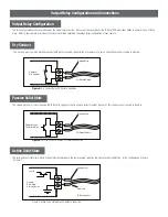
Page 8: ... I O Detect input needs to operate in one of three ways Refer to your camera user manual for more information regarding the output relay configuration of your camera Striped Wire I O Detect Cable Camera Dry Contact Passive Solid State The second method is similar requiring the IP Reset to supply current to an open collector output transistor This configuration is shown in Figure 6 Striped Wire I O...

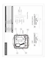
Page 9: ...ed for all devices Note 2 If the input connections need to be modified the striped wire is plus VDC and the solid wire is ground 0 VDC IPRS01 Serial 001656 Tested to comply with FCC standards Vin Vout Alarm 24Vac Red Red Blac k Brown Orange Orange B lack Black 12Vdc Red Red Blac k Orange Orange B lack Camera dome connection point IP Reset power box When you open the power box you will see the ipul...

Page 10: ...n input High Off input Low Red LED Operation Mode Indicator ON Intelligent Mode device operating as expected OFF Timed Mode Flashing Intelligent Mode device fault detected Hardware Installation cont LED Operation IP Reset Installation Software IP Reset installation software is available online for download at the following URL http www videolarm com content com videolarm pages Page 19 resources IP...

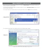
Page 11: ...k on the Add or Remove Programs software icon After a few seconds the following window will appear From the Add or Remove Programs menu below in Windows XP select the program IP Reset Click on the Remove button See screen shot below In response to the confirmation box Add or Remove Programs message Click Yes IP Reset In Windows XP XP PRO From the Uninstall or change a program menu in Windows Vista...

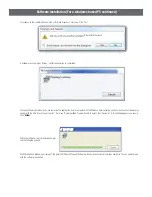
Page 12: ... based PC continued A window may show up as follows Let this window run to completion Following the above window if you are removing the application from a computer with the Windows Vista operating system a window not shown may appear with the title User Account Control It will say An Unidentified Program Wants to Access Your Computer if this window appears you should click Allow While the softwar...

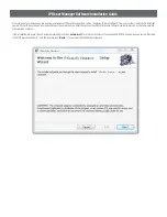
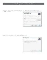
Page 13: ... of the networked computer that will run the IP Reset Manager Software computer must be on the same network with the video cameras If the installation file doesn t launch automatically Double click on setup msi file in the root directory of the supplied CDROM A window pops up saying Welcome to the IP Reset Setup Wizard click the box that says Next if you accept the registration statement IP Reset ...

Page 14: ... button just me is selected shown below than change it to the radio button Everyone as shown below A window will appear that says Confirm Installation Click Next to confirm the installation IP Reset By Videolarm IP Reset By Videolarm Files Videolarm IP Reset IP Reset By Videolarm IP Reset By Videolarm IP Reset By Videolarm ...

Page 15: ...may appear with the title User Account Control It will say An Unidentified Program Wants to Access Your Computer if this window appears you should click the Allow option IP Reset By Videolarm IP Reset By Videolarm Once installation completes the final window Installation Complete is launched Click Close to complete the installation process IP Reset By Videolarm IP Reset By Videolarm IP Reset By Vi...

Page 16: ...s desktop and may be launched by clicking the IP Reset desktop Icon shown below Once launched the IP Reset Configuration application resides in the users control tray on the bottom right hand side of the screen If the IP Reset application is enabled the Sunburst Icon will blink If the application is disabled the icon stays solid The user can then program IP Reset devices by using the mouse button ...

Page 17: ...ing directory C Program Files Videolarm IP Reset IP Reset_Software_User_s Guide pdf is the application manual used to configure IP Reset devices from the computer It describes installing the IP Reset devices to work with your cameras or other devices If you ever want to run the IP Reset software directly browse to the IP Reset installation Directory C Program Files Videolarm IP Reset and double cl...

Page 18: ...RP70TRAN11 N S IPRS01 IP Reset ...

Page 19: ......

Page 20: ...Appendix A IP Reset IP Camera Compatibility Chart Products IPRS01 PB24RS PB24BBRS ...

Page 21: ......

Page 22: ......

Page 23: ......

Page 24: ......

Page 25: ......

Page 26: ......

Page 27: ......

Page 28: ......

Page 29: ...Housings Poles Power Supplies and Accessories and 5 Years on camera systems SView QView Warriors and InfraRed Illuminators Register Your ProductsOnline Take a few moments and validate your purchase via the Online Product Registration Form at www videolarm com productregistration jsp Register your recent Moog Videolarm purchases and benefit from the following Simple and Trouble Free RMA process Add...

Reviews: