Moog ACV with CANopen bus interface
6 Signal routing and scaling
Digital outputs
B99224-DV018-D-211, Rev. A, October 2018
100
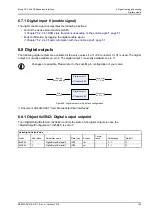
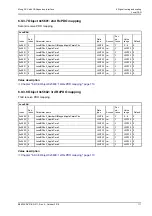
6.7.1 Digital input 0 (enable signal)
The digital enable signal incorporates the following functions:
• Control the device state machine (DSM).
Chapter "5.2.2.4.1 DSM state transitions depending on the enable signal", page 51
• Fault confirmation by toggling the digital enable signal.
Chapter "5.2.2.4.2 Fault confirmation with the enable signal", page 51
6.8 Digital outputs
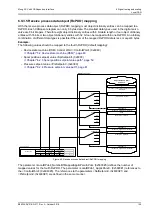
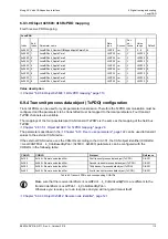
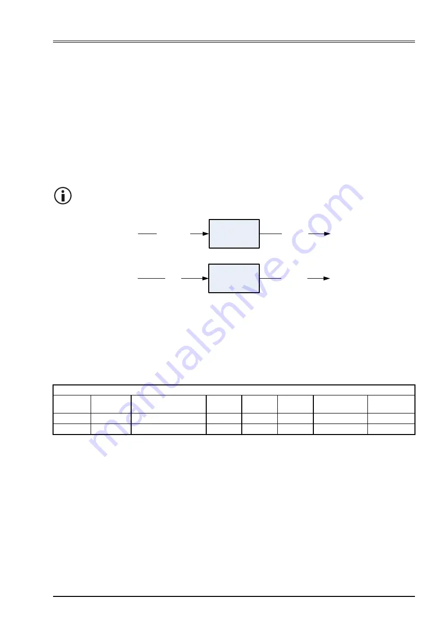
The following digital outputs are available for the servo valves if a 11+PE connector for X1 is used. The digital
output 0 is usually available on pin 8. The digital output 1 is usually available on pin 11.
Figure 39: Digital outputs in the default configuration
Document CA63420-001 "User Manual Electrical Interfaces"
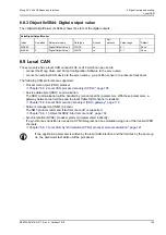
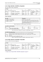
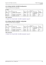
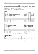
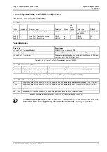
6.8.1 Object 0x5E42: Digital output setpoint
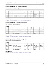
The <DigitalOutputSetpoint> (0x5E42) controls the state of the digital outputs in case the
<DigitalOutputConfiguration> (0x5E41) is set to 0.
Changes are possible. Please refer to the specific pin configuration of your valve.
Digital output 1
Digital output 0
Error
output
Connector
X1, Pin 8
Connector
X1, Pin 11
Enable
acknowledge
ValveDigitalOutputValue
Index
Sub-index
Parameter name
Data type
Access
Persis-
tence
Value range
Default
0x5E42
1
DigitalOutputSetpoint0
INT8
rw
-
0…1
0
0x5E42
2
DigitalOutputSetpoint1
INT8
rw
-
0…1
0


