Moog ACV with CANopen bus interface
6 Signal routing and scaling
Digital outputs
B99224-DV018-D-211, Rev. A, October 2018
101
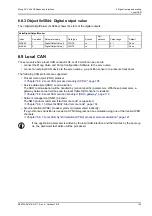
6.8.2 Object 0x5E41: Digital output configuration
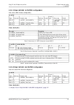
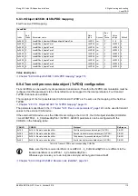
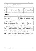
The behavior of the digital outputs can be configured by the parameter <DigitalOutputConfiguration>
(0x5E41).
Value description
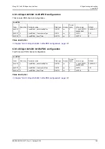
6.8.2.1 Object 0x2420: Digital output 1 type
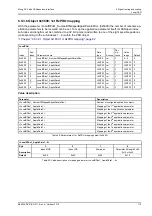
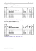
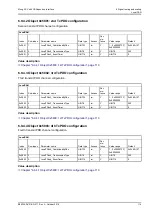
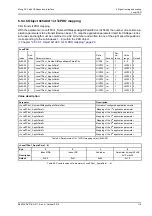
The <DigitalOutput1Type> (0x2420) is a copy of the <DigitalOutputConfiguration1> (0x5E41) and is used to
be compatible to old firmware versions.
ValveDigitalOutputType
Index
Sub-index
Parameter name
Data type
Access
Per-
sistence
Value range
Default
0x5E41
1
DigitalOutputConfiguration0
INT8
ro
-
0…4
3
0x5E41
2
DigitalOutputConfiguration1
INT8
ro
-
0…4
0
<DigitalOutputType>
Description
0
The servo valve's digital outputs are controlled by the parameter <DigitalOutputSetpoint> (0x5E42). The
pin can be used for special purposes.
1
Failsafe spool position monitoring on.
The digital output is controlled by the failsafe monitoring.
Chapter "7.15.5 Failsafe monitoring", page 241
2
Error output pin. The servo valve's digital output acts according to the Device Profile Fluid Power. This
means it is controlled by the device state machine (fault indication). In this case the digital output is used
to indicate fault states (negative logic).
Chapter "5.2.2.5 Error output pin", page 52
3
Enable Acknowledge. The digital output gets high (24 V) if the servo valve device state machine (DSM)
state is 'ACTIVE' (supply voltage is > 18 V, digital enable input is high, no fault will force the DSM to fault
state, …).
4
Control Deviation Monitoring. The digital output gets high (24 V) if the 'control deviation bit 11' of the
<StatusWord> (0x6041) is low. That means there is no control error.
Chapter "7.15 Monitoring", page 232
Table 53: Possible values of parameter <DigitalOutputConfiguration> (0x5E41)
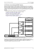
WARNING
Moving machine parts!
The word "failsafe" means not a personnel safety. Parts of the machine can move if the servo valve has a
fault.
If a personnel safety is needed, some additional electrical and hydraulic parts are necessary!
The availability of the digital output 1 (error output pin) depends on the servo valve model.
ValveDigitalOutputType
Index
Sub-index
Parameter name
Data type
Access
Persis-
tence
Value range
Default
0x2420
0
DigitalOutput1Type
INT8
ro
-
0…4
0


