Moog ACV with CANopen bus interface
7 Servo valve functions
Data logger
B99224-DV018-D-211, Rev. A, October 2018
253
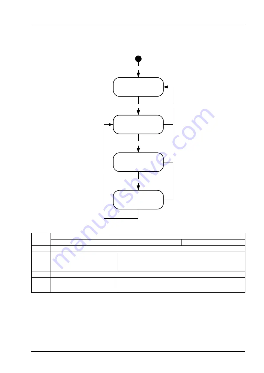
7.17.1 Data logger state machine
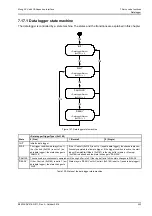
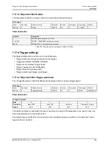
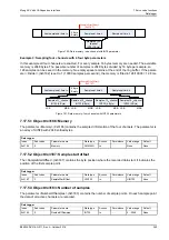
The data logger is controlled by a state machine. The states and the transitions are explained in this chapter.
Figure 147: Data logger state machine
'INIT'
<DataLoggerStatus>
(0x3181) = 0
TR0
'WAIT'
<DataLoggerStatus>
(0x3181) = 1
'SAMPLING'
<DataLoggerStatus>
(0x3181) = 2
'READY'
<DataLoggerStatus>
(0x3181) = 3
TR1
TR2
TR3
TR4
TR5
State
<DataLoggerTriggerType> (0x3188)
0 (Free)
1 (Normal)
2 (Single)
'INIT'
Initialize data logger.
'WAIT'
The trigger condition is always true. If
the <Control> (0x3180) is set to 1 (en-
able data logger), the state changes to
'SAMPLE'.
If the <Control> (0x3180) is set to 1 (enable data logger), the channels are con-
tinuously sampled to allow pre trigger. If the trigger condition is active, the start
index <SampleStartOffset> (0x3187) in the ring buffer memory <Memory>
(0x3186) is defined and the state is change to 'SAMPLE'.
'SAMPLE' The channels are continuously sampled until the ring buffer is full. If the ring buffer is full the state changes to 'READY'.
'READY'
If the <Control> (0x3180) is set to 1 (en-
able data logger), the state changes to
'WAIT'.
State stays in 'READY' until <Control> (0x3180) is set to 1 (enable data logger).
Table 100: States of the data logger state machine


