Moog ACV with CANopen bus interface
2 Access over CANopen
CANopen slave reference model
B99224-DV018-D-211, Rev. A, October 2018
9
2.3 CANopen slave reference model
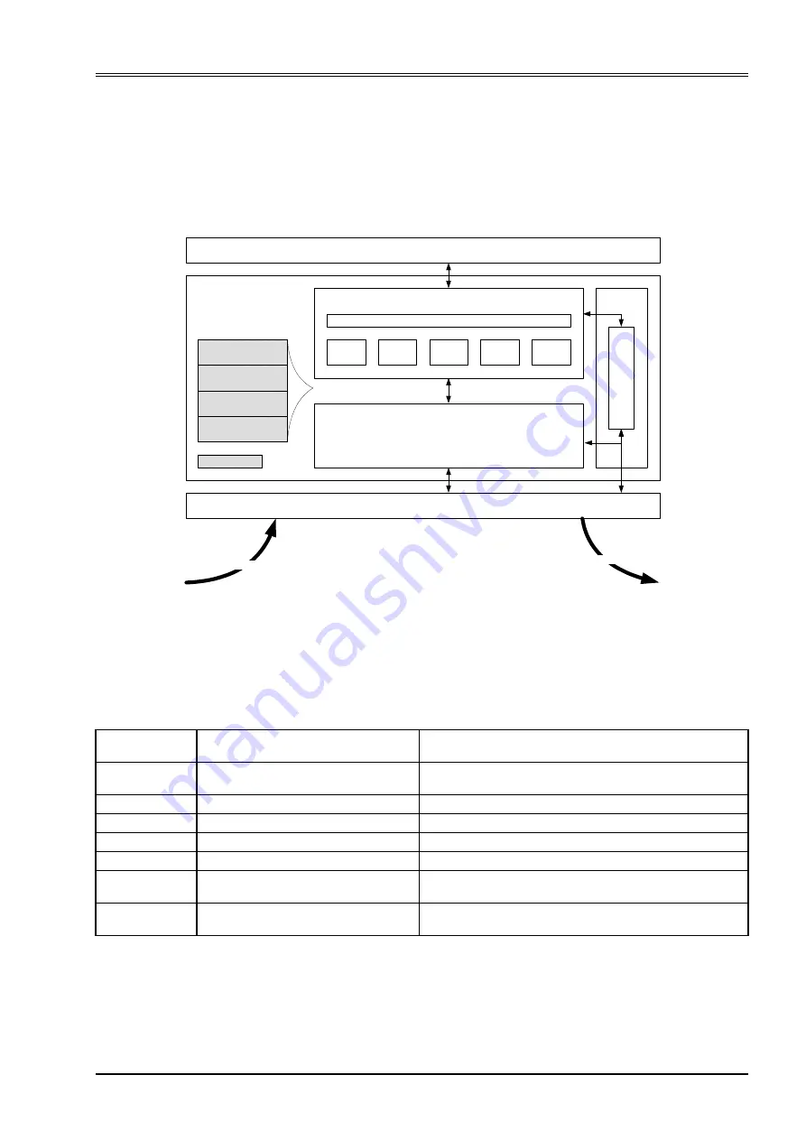
The architecture of the CANopen stack with Physical Layer (Phy), Data Link Layer (DL) and Application Layer
(AL) was taken from the ISO Reference Model (ISO/IEC standard 7498-1:1994). Layers three to six of this
7-layer reference model were not implemented, as these layers are intended for exchanging and sending tele-
grams. In a real-time field bus system, such functionalities are not required. The CANopen communication
concept can be described similar to the ISO/OSI reference model.
Figure 3: CANopen slave reference model
CANopen is based on the CAN data link layer and high-speed transceiver as specified in ISO 11898.
CANopen specifies in CiA 303-1 the bit-timing and recommends connectors and their pin-assignments.
CANopen represents a standardized application layer and communication profile as defined in CiA 301. The
CiA 305 specifies the layer setting services (LSS). These protocols are used to inquire or to change the set-
tings of the physical layer, data link layer and application layer on a device.
Object Dictionary (OD)
SDO
CANopen Application Layer (AL)
CAN Data Link Layer (DLL)
Layer
Management
Lay
er
S
e
tti
ng
Ser
vi
ce
(
LSS)
Servo Valve Controler Application
CAN Physical Layer (Phy)
Network Layer (NL)
Transport Layer (TL)
Session Layer (SL)
Pressentation Layer (PL)
CANopen Stack
Not implemented
CANopen
CANopen
PDO
EMCY
SYNC
NMT
Layer
Description
References
CAN / CANopen
Layer 7
Application layer
CiA 301 (CANopen application layer and communication profile)
CiA 305 (CANopen LSS)
Layer 6
Presentation layer (not implemented)
Layer 5
Session layer (not implemented)
Layer 4
Transport layer (not implemented)
Layer 3
Network layer (not implemented)
Layer 2
Data link layer
ISO 11898-1 (CAN)
CiA 305 (CANopen LSS)
Layer 1
Physical layer
ISO 11898-1/2/3/5 (CAN)
CiA 303-1 (CANopen Additional Specification)
Table 2: CANopen slave reference model

