Moog ACV with CANopen bus interface
3 Device structure
Overview
B99224-DV018-D-211, Rev. A, October 2018
37
3 Device structure
3.1 Overview
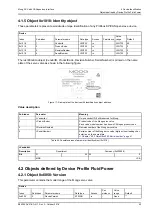
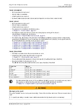
The servo valve functionality is based on the Device Profile Fluid Power. This profile defines the device
functionality and the object dictionary of the parameters. The following figure shows the general architecture.
Figure 15: Device structure
3.1.1 Device identification
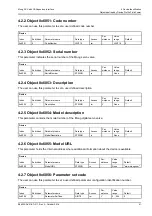
For the device identification (model number, serial number, device capability …) a special set of parameters is
defined.
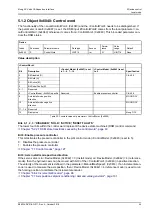
3.1.2 Device control
The device control block controls all functions of the device and contains the device state machine by which
the device functions can be activated or deactivated.
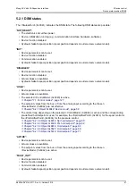
3.1.3 Signal routing and scaling
This block conditions the raw input signals for the signal processing and maps these to the internal servo
valve functions. This mapping depends among other things on the <DeviceMode> (0x6042) and the device
state machine state.
Servo valve functions
Demand value
generator
Event handler
Control modes
Monitoring
Signal routing and scaling
Setpoint value path
Actual value
transducer interface
Device control
Device state machine
Status display LEDs
Bootup of the device
Local mode
Interfaces
Local CAN bus
Field bus
Diagnostics
Fault reaction
Device identification
Stroring / restoring
parameters
Object dictionary
T
P
B
A
s
u
p
u
p
u
p
u
S
poo
l po
si
tion
de
m
and
v
al
ue
Spool position
actual value
Pr
es
su
re
act
ual
val
ues
Setpoint values
Actual values
Setpoint values
Actual values
Device mode
Control mode
Local mode
ControlWord
StatusWord
Fault reaction
Interfaces
Digital I/O
Analog I/O
Demand values
Actual values
Data logger
s
u
A
xi
s po
si
tion
act
ual
val
ue
Controller


