Moog ACV with CANopen bus interface
5 Device control
Local mode
B99224-DV018-D-211, Rev. A, October 2018
45
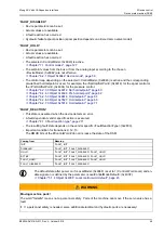
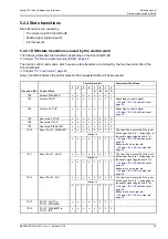
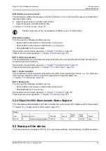
Bit 10: Axis install mode negative direction
If the servo valve is in <DeviceMode> (0x6042) = 3 (Install mode) or <DeviceMode> (0x6042) = 4 (reference
mode), then the hydraulic axis can be moved with bit 10 of the <ControlWord> (0x6040) in negative direction.
The velocity of the movement is defined in the parameter <ManualMaxSpeed> (0x5614). If an incremental en-
coder is used to measure the axis position then <DeviceMode> (0x6042) = 4 (reference mode) is used to run
the homing position to calibrate the incremental encoder.
Chapter "6.6.4 Incremental Encoder", page 96
Chapter "7.7 Axis position setpoint conditioning / demand value generator", page 191
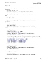
Bit 15: Ramp stop
If this bit is set, the spool position ramp and the pressure ramp output are frozen.
Spool position demand value generator:
Chapter "7.2.5 Ramp", page 140
Pressure demand value generator:
Chapter "7.4.5 Ramp", page 162
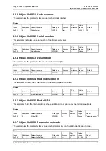
5.1.3 Object 0x4040: Local control word
Chapter "5.1.2 Object 0x6040: Control word", page 44
Value description
Same values as <ControlWord> (0x6040)
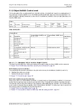
5.1.4 Object 0x403F: Local control word default
The <LocalControlWordDefault> (0x403F) defines the control word after power up of the digital servo valve.
During startup of the servo valve, the parameter <LocalControlWordDefault> (0x403F) is copied to the param-
eter <LocalControlWord> (0x4040).
Device
Index
Sub-index
Parameter name
Data type
Access
Persis-
tence
Value
range
Default
0x4040
0
LocalControlWord
UINT16
rw
N
UINT16
<LocalControl-
WordDefault>
(0x403F)
Device
Index
Sub-index
Parameter name
Data type
Access
Persis-
tence
Value
range
Default
0x403F
0
LocalControlWordDefault UINT16
rw
Y
UINT16
0x0107

