background image

5.6  Storage

The device contains plastic elements the proper-

ties of which may be changed by environmental

influences such as oxygen, ozone, heat, humidity,

light, UV rays and solvents.

Store the device under the following conditions:

n

Do not store near heaters or other sources of

heat.

n

Do not store in the same room with solvents,

chemicals, acids, fuels, disinfectants or similar

substances.

n

Do not store in the vicinity of fluorescent light

sources, mercury vapour lamps, light sources,

electric motors or devices which can generate

sparks or an ozone charge due to other elec-

trical discharges.

n

Do not expose to direct sunlight or open

installed fluorescent tubes which could gen-

erate a UV load.

n

Do not place on copper, brass or rusty steel.

n

Store in a dry and dust-free place.

n

If possible, store in air and light-resistant orig-

inal packaging and only unpack shortly before

use.

n

Storage temperature: 5 to 25 

n

Relative humidity: 65 %

n

Spare seals: Store without strain, do not bend,

fold, knick, hang on hooks or expose to pres-

sure loads.

n

Maximum storage time: 12 months. After that,

send back to manufacturer for inspection.

Under some circumstances, there are

notes about storage on the packaging

pieces which exceed the requirements

named here. Adhere to these accordingly.

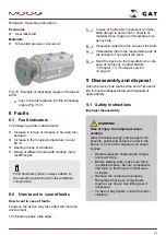
6  Installation and initial com-

missioning

6.1  Safety instructions

 WARNING!

Risk of injury from missing media line
connections!

Media may leak if connections are made

incorrectly. Contact with the leaked media

can cause serious injuries.

– Connect the media and leak connec-

tions properly to the corresponding

supply aggregates.

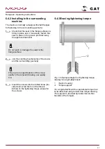
– Adhere to the engraved markings for

the connection bores on the housing

and clearly identify the connections

using the information in the drawings

included with delivery.

 CAUTION!

Risk of crushing from the dead weight
of the component!

If the device falls down during assembly, it

can crush hands or feet due to its weight.

– Handle the device carefully. Do not let

it fall. If necessary, secure it with a suit-

able hoisting device.

– Wear safety shoes.

Rotopack • Operating instructions


18

Summary of Contents for GAT Rotopack BAT

Page 1: ...Rotopack Operating instructions...

Page 2: ...e 49 6722 93788 0 Fax 49 6722 93788 110 Email ig de ge info moog com Internet www gat mbh de Moog and GAT are registered trademarks of Moog Inc All trademarks as indicated herein are the property of M...

Page 3: ...3 3 PV diagram 10 4 Construction and function 12 4 1 Type key 12 4 2 Description 13 4 3 Rotopack MCR 13 4 4 Rotopack MC 13 4 5 Rotopack MCG 14 4 6 Rotopack MCVR 14 4 7 Rotopack M 14 4 8 Rotopack BAT...

Page 4: ...itial commissioning 23 7 Maintenance 23 7 1 Safety instructions 23 7 2 Maintenance schedule 23 7 3 Maintenance work 24 7 3 1 Cleaning the device 24 7 3 2 Checking the media lines 24 7 3 3 Re lubricati...

Page 5: ...on on the device n Enclosed test reports n Order documents n Drawings n Type plate n Operating instructions for the additional compo nents optional Rotokombi 1 2 Explanation of symbols Safety instruct...

Page 6: ...our prod ucts 2 Safety 2 1 Proper use Rotopack rotary feedthroughs are used for leak free transfer of media only These instructions the type plate the order documents and drawings are recognised as va...

Page 7: ...ing the movements to a standstill and secure against switching on In the danger zone wear close fitting protective clothing with low tear strength Rotokombi WARNING Danger of injury due to rotating pa...

Page 8: ...or third parties during operation The device is used in the commercial sector The owner of the device is therefore subject to the legal occupational safety requirements The following in particular ap...

Page 9: ...venting pos sible hazards independently due to their specialist qualification knowledge and experience of han dling rotary feedthrough and familiarity with the valid standards and regulations Transpor...

Page 10: ...performance data depend on the specific version Refer to the type plate the order documents and any drawings which may also be included for this information A data sheet is available for standard dev...

Page 11: ...PV diagram provides an overview of the correlation between the operating pressure and the speed for various rotary feedthrough seal diameters The specified values are reference values only The actual...

Page 12: ...ways required Connection thread pressure connection specification always required 04 1 8 06 1 4 10 1 2 16 3 4 20 1 25 1 1 4 Material specification always required S Steel K Nickel plated I Stainless s...

Page 13: ...asic version in the Rotopack series This series is characterised by shafts with rolling bearings The rolling bearings are sealed off from the environment with radial shaft seals The basic version devi...

Page 14: ...ich is adapted to the operating conditions Area of application Gas air water The typical area of application is at pressure levels of up to 1 MPa 4 7 Rotopack M Brief description Rotopack M devices wh...

Page 15: ...operating instructions for all the devices used The combination with other components and transfer of other media may cause additional haz ards If necessary the owner must take additional measures 5 T...

Page 16: ...aged in accord ance with anticipated transport conditions Only environmentally friendly materials have been used in the packaging The packaging is intended to protect the individual components from tr...

Page 17: ...are fastened on pallets can under the following conditions be transported with a fork lift n The fork lift must be engineered for the weight of the packages n The package must be fastened securely to...

Page 18: ...Spare seals Store without strain do not bend fold knick hang on hooks or expose to pres sure loads n Maximum storage time 12 months After that send back to manufacturer for inspection Under some circ...

Page 19: ...ion NOTICE Risk of material damage from static overdetermination Static overdetermination is generated by screwing the rotor and stator to the sur rounding If no suitable measures are taken to prevent...

Page 20: ...switched back on 3 Allow hot components to cool down as necessary 4 Check the entire installation environment of the device to ensure that it is isolated from the voltage and depressurised Switch off...

Page 21: ...the surrounding geometry If there are no specifications of the screw quality in the relevant drawing use quality 8 8 3 Insert the screws into the drilled holes pro vided and screw them not the thread...

Page 22: ...red continuously Foreign bodies which are larger than 25 m must be fil tered off The service life of the sealing elements is influenced significantly by the filtering of the operating medium The speci...

Page 23: ...connections as necessary 4 Re establish all connections 5 Carry out initial commissioning as per Chapter 6 5 Initial commissioning on page 22 7 Maintenance 7 1 Safety instructions WARNING Risk of inju...

Page 24: ...lean dry and lint free cloth 1 Switch off all mechanical movements elec trical lines and media supply lines and secure them to prevent them from being switched back on 2 Clean the exterior of the hous...

Page 25: ...gger an immediate emer gency stop 2 If possible determine the cause of the fault 3 Immediately inform the responsible party at the location of use about the fault 4 Send the device to the manufacturer...

Page 26: ...nt Be aware of the weight 8 Collect any leaked media 9 Re use media or dispose of them properly Refer to the safety data sheets for the media as necessary 9 3 Disposal If no return or disposal agreeme...

Page 27: ...delivery 16 Installation 20 L Loads 15 Lubricating 24 M Maintenance schedule 23 Maintenance work 24 Measures in case of leaks 23 Misuse 6 O Operating conditions 10 Options 15 Owner 8 P Packaging 16 Pr...

Reviews: