Page 30
LP User’s Manual - The User Interface
Page 31
LP User’s Manual - The User Interface
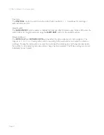
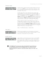
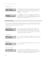
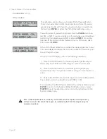
MOD SOURCE 5 (MOD SRC 5):
This menu allows you to select one of two modulation options that
will be used when the FILT ENV source is selected on the front panel
(Modulation Source 5). The Filter Envelope (FILT) is the default source,
but Sample & Hold (S-H) can be choosen as an alternate. To change
the parameter, use the
CURSOR
button to highlight the parameter,
then use the
VALUE
knob to set the new parameter value.
Values: FILT, S-H
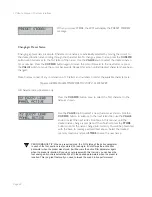
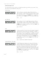
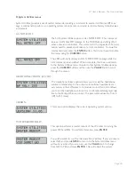
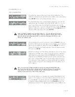
MOD SOURCE 6 (MOD SRC 6):
This menu allows you to select one of two modulation options that
will be used when the OSC2 source is selected on the front panel
(Modulation Source 6). Oscillator 2 (OSC2) is the default source, but
Noise can be choosen as an alternate. To change the parameter, use
the
CURSOR
button to highlight the parameter, then use the
VALUE
knob to set the new parameter value.
Values: OSC2, NOISE
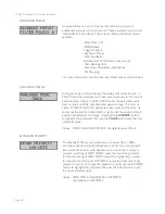
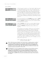
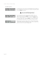
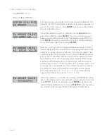
PITCH BEND (PB):
The Pitch Bend menu allows you to individually set the positive and
negative ranges for the Pitch Wheel. The settings are specifi ed in
semitones. To change either parameter, use the
CURSOR
button to
highlight the parameter, then use the
VALUE
knob to select the new
parameter value.
Values: UP: 0, +2, +3, +4, +5, +7, +12
DN: 0, -2, -3, -4, -5, -7, -12
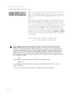
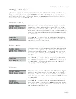
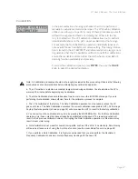
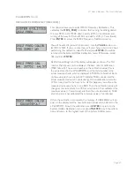
MODULATION DESTINATION 2 (MOD DEST2):
This menu allows you to program a secondary destination for
modulation. The four destination options here are the same as
those offered on the front panel (the primary modulation). The
Modulation
AMOUNT
control specifi es both the primary and
secondary modulation amounts - there is no separate amount control
for the secondary modulation. To program a secondary modulation
destination, use the
CURSOR
button to highlight the destination
parameter, then use the
VALUE
knob to set the new parameter value.
Values: OFF, PITCH, FILTER, WAVE, OSC2

