Page 8
LP User’s Manual - The Basics
Page 9
LP User’s Manual - The Basics
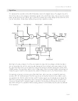
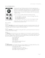
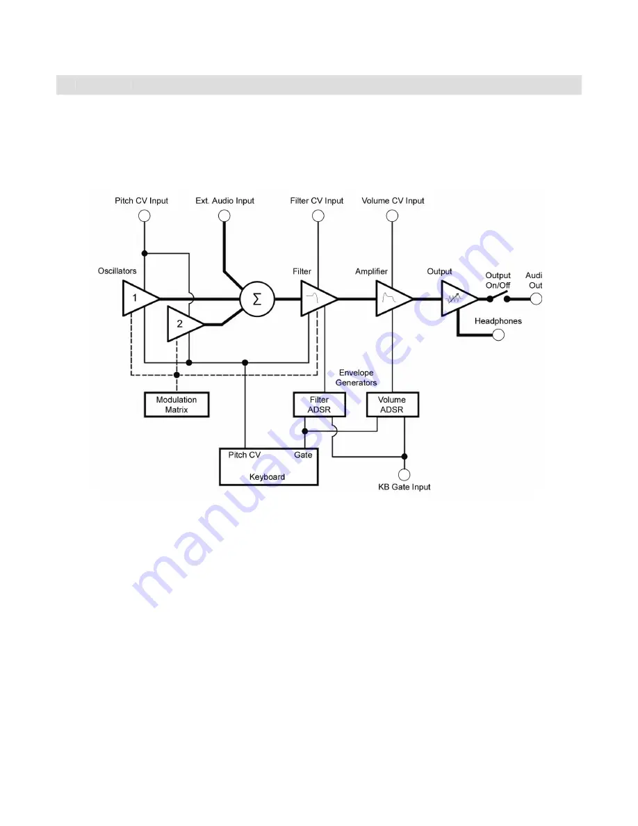
To understand the operation of the Little Phatty, take a look at the diagram below. The diagram shows the
fl ow of the audio, control voltage and modulation signals in the Little Phatty. Heavy lines are used to indicate
audio signals, which fl ow from left to right. Lighter lines indicate the control voltages (CV’s), which fl ow from
the top and bottom. Dotted lines indicate programmable modulation routings.
Referring to the above diagram, the LP’s source signals are created by two voltage-controlled oscillators
and are mixed together with the external audio input signal. This combined audio signal is passed to the
low-pass fi lter, where the tone is sculpted according to the settings of the fi lter parameters and the Filter
ADSR envelope. The signal then passes to the amplifi er stage, where the Volume ADSR envelope shapes it.
Finally, the signal is routed to the output section, where the fi nal level is set by the Master Volume control.
The keyboard is the main control source of the Little Phatty. Each time a key is pressed, the keyboard
produces Pitch CV and Gate signals. The Pitch signal is used to specify the pitch of the oscillators, and is
also applied to the Filter to control the fi lter cutoff. The Gate signal is used to simultaneously trigger the
Filter and Volume Envelope Generators. The LP can also be controlled through a MIDI connection (not
shown), or through the CV and Gate trigger connections. The resulting sound depends on the various
parameter settings of the oscillators, fi lter, envelope generators and modulation matrix, plus any additional
CV connections.
Signal Flow


