7.9 V/
Hz
mode
A simple function test can be carried out in V/f mode. This test will show users
whether a motor is connected correctly and whether the right direction of movement
will be followed. If ...
The direction of movement is the wrong one,
The motor is at a standstill,
Uncontrollable motion occurs,
then the connection and the motor data need to be checked.
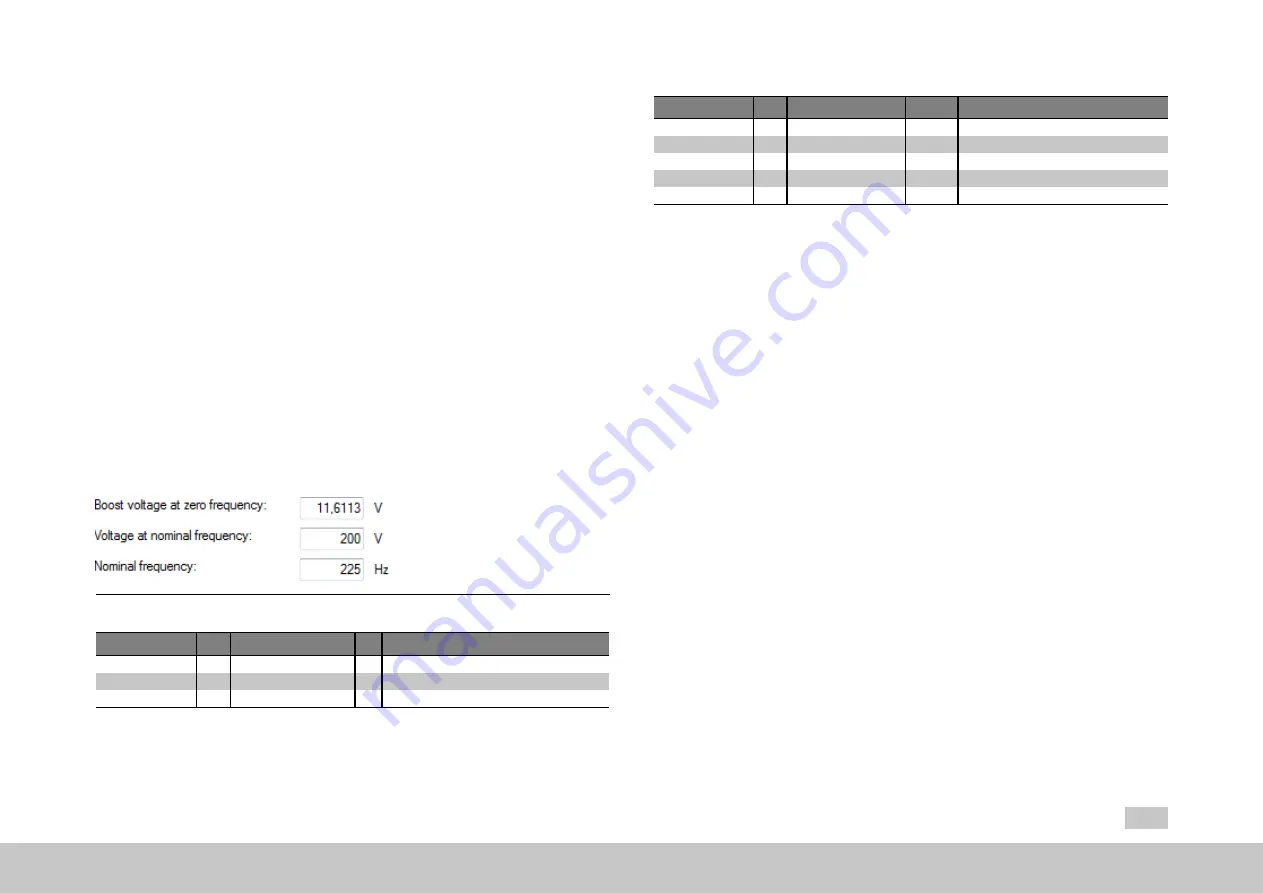
For testing purposes, a V/f control system is implemented in such a way that the
closed-loop speed control circuit will be replaced by the V/f control. The reference is
the speed reference; the actual speed is set equal to the reference. A linear
characteristic with two nodes has been implemented, with a fixed boost voltage
setting P 313[0] - CON_VFC_VBoost at 0 Hertz. Starting from the rated frequency
P 314[0] - CON_VFC_FNom, the output voltage will remain constant at P 315[0] -
CON_VFC_VNom. This means that an asynchronous motor will automatically be
driven to field weakening as the frequency rises.
Fig. 7.40: “V/f mode” dialog box
ID
Index Name
Unit Description
313
0
CON_VFC_VBoost
V
V/f characteristic: Boost voltage
314
0
CON_VFC_FNom
Hz
V/f characteristic: Rated frequency
315
0
CON_VFC_VNom
V
V/f characteristic: Nominal voltage
Table 7.
30
: “V/f mode” parameters
MOOG
ID
No.:
CB40859-001
Date:
02/2018
MSD Servo Drive - Device Help
153
7 Control
ID
Index Name
Unit
Description
19
0
epsRS
Pole width Rotor/stator electrical angle
20
0
freqRS
Hz
Rotor/stator electrical frequency
21
0
freqFS
Hz
Field/stator electrical frequency
29
0
vmot
V
Current motor voltage
312
0
CON_CCON_VMot
V
Current motor voltage (rms, phase-to-phase)
Table 7.
31
: Scope signals “V/
Hz
mode (basic)”


