NOTE
Always discuss the use of sine wave filters with your Moog project
support representative.
5.7.2 Configuration
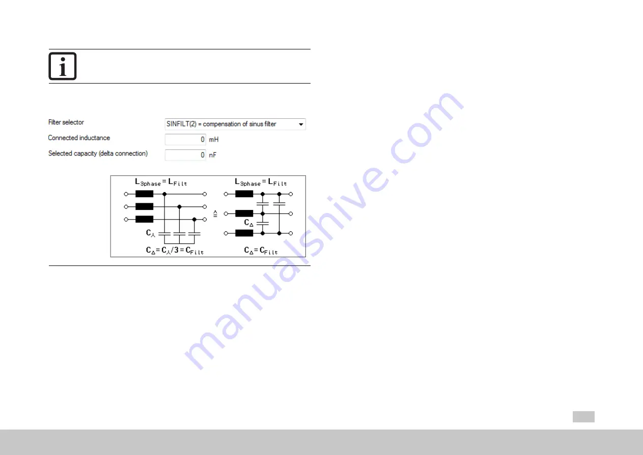
Fig. 5.16: “Motor filter” dialog box
Filter support can be enabled by setting P 2900[0] - MOT_Filt_Sel to one of the
following settings:
MOT_Filt_Sel = (OFF)0
No filter compensation. The current controller decoupling network will be active.
MOOG
ID
No.:
CB40859-001
Date:
02/2018
MSD Servo Drive - Device Help
47
5 Motor
MOT_Filt_Sel = (MCHOKE)1
Has no effect on the current setpoint calculation. Instead, it just deactivates the
current controller decoupling network. If necessary, the calculated motor terminal
voltage components (before the voltage drop caused by the motor choke) can be
viewed using scope signals usdmot_SinFilt, usqmot_SinFilt. If there are no negative
influences on the current control stability, it is recommended not to use this setting.
Instead, you can select MOT_Filt_Sel = 0 and add the motor choke’s inductance to
the value in MOT_Lsig.
MOT_Filt_Sel = (SINFILT)2
Ensures that the capacitor current components will be calculated based on the
above equations and that they will be added to current setpoint components isdref,
isqref. Moreover, the current controller decoupling network will be deactivated. The
calculated values of the motor terminal voltage and capacitor current components
can be viewed with scope signals usdmot_SinFilt, usqmot_SinFilt and isdpre_SinFilt,
isqpre_SinFilt respectively.


