Code
and
Mode
are used to set SSI modes. If Mode=1, wire break monitoring
(if any) will be disabled, for example. If
Mode
= 0, it will be enabled instead
(default).
In the case of linear encoders,
PeriodLen
and
DigitalResolution
will be
needed instead of
MultiT
and
SingleT
.
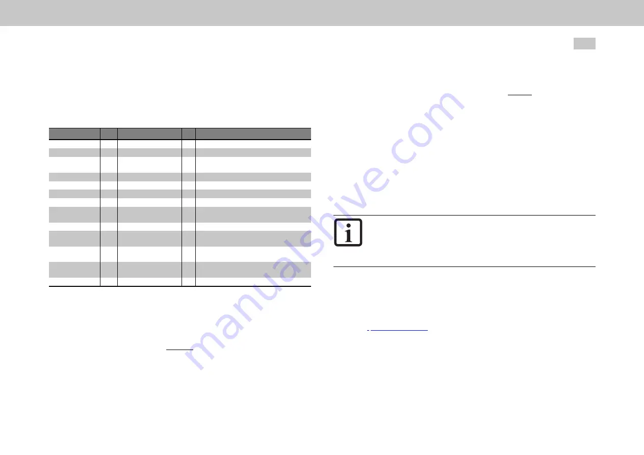
P No.
Index Name / Setting
Unit Description
505
0
ENC_CH1_Sel
Main selection on encoder channel Ch1
540
0
ENC_CH1_Abs
Absolute value interface for one-time reading
542
0
ENC_CH1_lines
Number of analog Sin/Cos lines per revolution
(TTL lines as well).
543
0
ENC_CH1_MultiT
Number of multi-turn bits for the digital interface
544
0
ENC_CH1_SingleT
Number of single-turn bits for the digital interface
545
0
ENC_CH1_Code
Code selection (for SSI encoders) (binary, Gray)
546
0
ENC_CH1_Mode
Mode selection (for SSI encoders)
547
0
ENC_CH1_MTBase
Definition of point of discontinuity in multi-turn
range
548
0
ENC_CH1_MTEnable
Enable MultiTurn use (negative logic, 1=MToff)
551
0
ENC_CH1_EncObsMin
Comparison value for Sin/Cos wire break
monitoring
553
0
ENC_CH1_PeriodLen
nm
Linear encoders: Length of an analog Sin/Cos
segment in nm (nanometres)
554
0
ENC_CH1_
DigitalResolution
nm
Linear encoders: Length of a digital increment in
nm (nanometres)
616
0
ENC_CH1_CycleCount
Sampling cycle in: n x 125 μ (microseconds)
Table 6.6: Main parameters for encoder channel Ch1
MTBase, when used with its default setting, will ensure that the absolute value
initialization “starts up with plus-minus”: I.e. the encoder’s multi-turn value range
from 0 to max will be mapped to -1/2max to +1/2max; the second half of the
measuring range will be initialized as negative; in this case, the point of discontinuity
will be found at 1/2max. --- this can be changed with MTBase! --- When MTBase=0,
the absolute value initialization will, for example, “start up with zero to max”: I.e. the
MOOG
ID
No.:
CB40859-001
Date:
02/2018
MSD Servo Drive - Device Help
58
6 Encoder
encoder’s multi-turn value range from 0 to max will be mapped to 0 to max; the
second half of the measuring range will be initialized as positive; in this case, the
point of discontinuity will be found at 0.
If you set MTEnable to 1, you can use an available multi-turn encoder as a single-
turn encoder (this is only needed for testing purposes).
If you set EncObsMin to 0, Sin/Cos wire break monitoring will be disabled. The
default value is 0.2 (20 %) and stands for a calculated amplitude value (calculated
using the two Sin/Cos signals) of x = sqrt(a^2 + b^2). If the Sin/Cos signals are equal
to approx. 1 Vss in comparison, approx. 0.8 will be calculated here (approx. 80 %
magnitude at the A-D converters; approx. 0.25 Vss Sin/Cos will yield approx. 0.2
here (20 % magnitude at the A-D converter)). The error threshold can be set with
EncObsMin within a broad range.
NOTE
As there are various protocol modes available for SSI encoders
(with/without wire break monitoring, with/without parity bit, etc.),
consult with your project supervisor or the Helpline Moog before
using any special SSI protocol modes.
6.5.2 EnDat (cyclical) X7
Ch1: ENDAT(4) - Cyclical EnDat (2.1 or 2.2)
EnDat is a digital encoder interface developed by HEIDENHAIN. For more details,
please visit
and go to ►Dokumentation ►Fundamentals
►Interfaces ►EnDat 2.2
The software versions required to run the EnDat encoder interface are the standard
software versions for the MSD Servo Drive and MSD Single-Axis Servo Drive
Compact.


