background image

53

OUTPUT

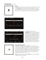
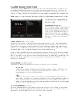
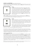
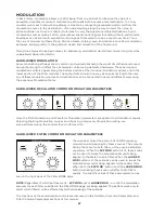
The Output module contains two volume knobs, one to control the 

MASTER VOLUME 

(

MAIN L/R


outputs), and one to control the 

HEADPHONES

 output level. Each knob functions independently; 

turning the 

MASTER VOLUME

 down and the 

HEADPHONES

 level up allows Moog One settings and 

sounds to be cued up, or auditioned privately without the need to change any external mixer settings 
or connections. The 

MASTER VOLUME

 and

 HEADPHONES

 knobs are global for the entire Moog One. 

Unlike every other knob on the Front Panel, these knobs always display their true value in a “what you 
see is what you get” manner.

MASTER VOLUME 

(0 to 10)

The 

MASTER VOLUME

 knob controls the 

MAIN L/R

 output level of 

Moog One. Higher values will have a higher volume level.

HEADPHONES 

(0 to 10)

Moog One provides two identical headphone jacks, located on the 
front edge of the Left Hand Controller panel. This 

HEADPHONES


knob controls the volume level of the 

HEADPHONES

 jacks, which 

are not affected by the 

MASTER VOLUME

 knob. This allows you to 

check or tweak a Preset with headphones on stage without allowing 
the audience to hear it until you’re ready to turn up the 

MASTER 

VOLUME

 knob.

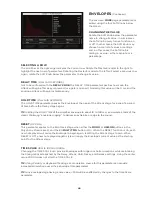
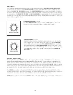
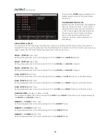
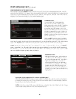
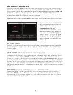
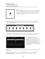
OUTPUT MORE PAGE

Pressing the triangular 

MORE

 button in the upper right corner of the OUTPUT module will reveal a 

second level of parameters that can be accessed and modified using the interactive portion of the 
Center Console. These additional parameters are displayed in the bottom portion of the screen.The 
left pane displays output assignments for each Synth and for each of the 

EXT. INPUT

 jacks, as well as 

the volume level of each output. The right pane shows the current value of the Front Panel hardware 
parameters for this module. Tweaking these panel controls will update their values here.

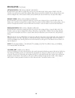
The 

MORE

 parameters of the global OUTPUT module designate the routing for each Synth in the 

current Preset. Output Routing for the Insert channels is one-to-one, meaning each Synth can only be 
assigned to one Insert at a time, and each Insert can only host one Synth at a time.

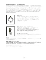
NOTE: 

Pressing the (now) illuminated 

MORE

 button will exit the MORE page and recall the HOME screen.

Summary of Contents for One

Page 1: ...o find the most up to date manual If you are having trouble finding specific information about your Moog One in this manual please email moogonemanual moogmusic com for assistance THIS VERSION WAS PUBLISHED ON 1 10 19 Revisions made to Page 52 Spread Parameter Page 100 Stereo Width Page 129 Noise Reduction ...

Page 2: ......

Page 3: ... Dr Robert Moog M u s i c a l i n s t r u m e n t s p rov i d e t h e m o s t e f f i c i e n t a n d re f i n e d i n te r f a c e b e t we e n h u m a n a n d m a c h i n e o f a ny t h i n g we k n ow ...

Page 4: ...the outlet when left unused for a long period of time or during lightning storms 8 Care should be taken so that objects do not fall and liquids are not spilled into the enclosure through openings There are no user serviceable parts inside Refer all servicing to qualified personnel only NOTE This equipment has been tested and found to comply with the limits for a Class B digital device pursuant to ...

Page 5: ...erformance Set Master Clock Voice Allocation Hold Chord Polyphony Modulation Arpeggiator Sequencer Effects Left Hand Controller THE BROWSER Loading A Preset Loading A Timbre Saving Presets And Synth Timbres EDITING AND SAVING Compare Snapshot Autosave SETTINGS Global MIDI Control CV Inputs CV Outputs Utilities Library Tuning SPECIFICATIONS SERVICE AND SUPPORT 07 07 08 09 09 10 10 17 19 22 22 29 31...

Page 6: ...This page left intentionally blank ...

Page 7: ... detachable IEC style power cable Connect the included IEC power cable to the Moog One power supply Connect the power supply cable to the 19 volt DC locking connector on the rear panel of Moog One Connect the other end of the power cable to a suitable AC wall outlet with a protective earth ground connection Finally use the power switch on the rear panel to turn on your new Moog One NOTE The power ...

Page 8: ... 1963 Moog analog circuits have been renowned for their rich harmonic qualities and for the organic nature of their expression POLYPHONIC Synthesizers changed forever with the advent of polyphony As a polyphonic synthesizer Moog One can independently articulate numerous voices simultaneously up to 8 or 16 depending on the configuration of your instrument This voice count designation is stamped on ...

Page 9: ...can be easily synced to the Master Clock or allowed to run freely In addition each Synth contains its own distinct sound settings note range voice count MIDI Channel and more Collectively these settings and parameters that define an individual Synth are referred to as a Timbre There are two types of audio effects in Moog One Synth Effects and Master Effects Each Synth has a dedicated Synth Effect ...

Page 10: ...urther extends the dynamic playability of this powerful analog instrument Around back the Moog One Rear Panel is home to a vast array of audio analog control voltage and expression input and output jacks as well as MIDI USB and Ethernet ports FRONT PANEL The Front Panel is divided into three sections the Left Panel the Center Console and the Right Panel The Front Panel is always active in that tur...

Page 11: ...lucent button will toggle its function On the LED being lit and Off while pressing a solid red button selects a function state or option as indicated by a lit LED on the panel MORE Nearly every module is equipped with a triangular MORE button located in its upper right corner When a MORE button is pressed the Center Console Display screen reveals additional parameters specific to that module These...

Page 12: ...ily In general parameters are displayed above their respective Soft Knobs in groups of four Here values can be edited using the four Soft Knobs If more than four parameters are available rotating the Master Encoder will call up the additional rows Together the Soft Buttons Soft Knobs and Master Encoder provide effortless navigation of the graphic interface Surrounding the Master Encoder are eight ...

Page 13: ...n the modulation source signal or to square or cube the modulation source control signal to further expand the variation and expressivity of the Moog One s powerful modulation engine NOTE When editing or creating a Modulation Matrix pressing down on the Master Encoder will toggle back and forth between two sets of parameters upper and lower available for each modulation routing DELETE The DELETE b...

Page 14: ...formed by holding down the SHIFT button as you operate the controls Alternatively you can enter SHIFT mode by pressing and releasing the SHIFT button The button will blink and any operation performed will behave as if the SHIFT button is being held Moog One will remain in this state until the SHIFT button is pressed again and the blinking has stopped WORKING WITH SYNTHS Tweaking knobs and pressing...

Page 15: ...G0 to C10 MIDI Note 0 127 TIP Press any SYNTH button while holding SHIFT to solo the selected synth Repeat to return to standard behavior ADDING EXPRESSION The Expression Assign buttons provide a convenient way to instantly assign a controller as a modulation source to a specific parameter Simply press any Controller button in the Expression Assign module and then tweak a knob or press a button to...

Page 16: ...nt Performance Set is always accessible from the lower Right Panel Each Performance Set can recall up to 64 Presets that are arranged in eight Banks A H of eight Presets 1 8 Performance Sets allow you to have select Presets ready and on tap for instant access during a live performance or even a studio session To assign the active Preset to the currently loaded Performance Set simply press the Bank...

Page 17: ... Glide delivers a smooth continuous change in pitch when moving from one note to the next In addition to the GLIDE RATE knob and the GLIDE ON button Moog One offers three types of Glide as well as additional parameters for Legato Glissando and Gated Glide Pressing the MORE button on the Left Hand Controller brings these parameters into view in the Center Console Display X Y PAD The X Y PAD is a hi...

Page 18: ...ontroller that is most commonly used to manually determine the amount of modulation being applied from a Source to a Destination In the case of the Moog One the MOD wheel can also be assigned to multiple locations simultaneously through the Mod Matrix and EXPRESSION ASSIGN Buttons NOTE The MOD wheel position can be saved as part of the Preset HEADPHONES Located just below the X Y PAD is a pair of ...

Page 19: ...t affected by the MASTER VOLUME knob INSERT 1 2 3 4 Four INSERT jacks are provided Their routing is controlled by pressing the Output Module MORE button The tip of this tip ring sleeve jack is wired as the Send so each INSERT jack can be used as an individual output when used with a standard unbalanced TS 1 4 cable Each Insert jack can also be used with a Y configuration insert cable to achieve tr...

Page 20: ...l that allows the parameters and functions on one instrument to interact with the parameters and functions of another instrument in the analog domain In the days before MIDI and USB control voltage was the primary method for interconnection between synthesizers and it is still the primary method of interfacing with modular and Eurorack synthesizers today Moog One is equipped with two dedicated CV ...

Page 21: ... requires no additional software drivers into Moog One operations The USB port found here allows Moog One to communicate directly with your computer via USB sending and receiving MIDI and other system data PEDAL JACKS Moog One includes three pedal input jacks One is configured as a sustain SUSTAIN pedal input and the other two as expression EXP 1 EXP 2 pedal inputs These inputs can be used to cont...

Page 22: ...sed harmonic diversity The second waveform is a Pulse wave with a variable Pulse Width As with the PULSE WIDTH knob the TRI SAW WAVE ANGLE knob can be modulated from another controller or parameter Together their combined signals can be used to create an endless array of wave shapes that determine each Oscillator s final sonic output The OLED screen in the center of each Moog One Oscillator provid...

Page 23: ...the WAVE button selection TRI TRIANGLE MODE With the WAVE button set to TRI the TRI LED will be lit rotating the WAVE ANGLE knob will continually vary the wave shape changing the relationship between the rising and falling segments of the wave The center position will create a Triangle wave Rotating the knob to the far left will produce a wave shape closer to a Sawtooth wave rotating the knob to t...

Page 24: ...pulse with a long duty cycle NOTE The inverse of a narrow Pulse Wave with a 20 on time is a wide Pulse Wave with a 20 off time Graphically they are mirror images of each other and their harmonic contents are identical However it is the smooth cyclic transition from one to the other that gives Pulse Width Modulation PWM its distinctive sound MIX Using the MIX knob you can create a unique and intric...

Page 25: ...e static image displayed on the screen is created by the Oscillator s parameter settings only and does not reflect any real time modulation routings that may also be affecting the final waveform The right pane shows the current value of the Front Panel hardware parameters for this module NOTE Pressing the now illuminated MORE button will exit the MORE page and recall the HOME screen CHANGING THE V...

Page 26: ...arate values for Bend Up and Bend Down and each can be set to either a positive or a negative value In this way the Pitch Bend wheel can be used to resolve each oscillator to a specific note or interval at either end of its travel allowing for creative harmonies and chords to be introduced as part of a performance BEND UP OFFSET 24 to 0 to 24 This parameter specifies the amount of Pitch Bend Offse...

Page 27: ...gnal rotating the knob to the left inverts the amount of MOD EG signal RING MOD RING MODULATOR Ring Modulation analyzes two input signals to create a new complex output signal Mathematically this output signal is the combined sum and difference of the frequencies of the input signals Ring Modulation is known for creating metallic robotic and inharmonic sounds The output of the RING MOD appears in ...

Page 28: ...FREQUENCY MODULATION Frequency Modulation FM allows the output of one oscillator to modulate the frequency of another oscillator Applying FM can produce complex sounds and introduce interesting harmonics Moog One uses linear FM FM AMT 0 to 10 Turning this knob determines the amount of Frequency Modulation that is applied from one Oscillator to another The higher the value of this knob the deeper t...

Page 29: ...he ATTACK knob sets the Attack Time of the Noise Envelope Generator controlling how fast the Noise reaches its maximum volume once a key has been pressed or a gate signal received RELEASE 1 M SEC TO 10 SEC The RELEASE knob sets the Release Time of the Noise Envelope Generator controlling how slowly the NOISE fades out after a key is released or the gate is closed SUSTAIN ON LIT OFF UNLIT When the ...

Page 30: ...re selected WHITE PURPLE White Noise and Purple Noise are selected WHITE NOISE White Noise is analogous to white light it contains the same amount of energy across every octave band in the audio spectrum It s the sound you hear when an old television is set to a non existing channel RED NOISE Also referred to as Brownian Noise Red Noise provides a 6 dB decrease in energy per octave across the audi...

Page 31: ...nters the Mixer Press the associated SVF and LADDER buttons to specify which FILTER s Oscillator 1 is being routed to When an SVF and or LADDER button is lit it is On and that filter path is enabled OSC 2 Use the OSC 2 knob to set the level of the Oscillator 2 signal as it enters the Mixer Press the associated SVF and LADDER buttons to specify which FILTER s Oscillator 2 is being routed to When th...

Page 32: ...eters for this module The final Mixer input channel is labelled External and has no corresponding Front Panel hardware Instead this input is controlled using the first three Soft Knobs at the bottom edge of the screen NOTE Pressing the now illuminated MORE button will exit the MORE page and recall the HOME screen The onscreen MORE page parameters are edited using the soft knobs below the screen CH...

Page 33: ... frequency limit lower frequency limit or center frequency value depending on the Filter MODE selected The RESONANCE knob routes a portion of the Filter s output signal back to the input of the Filter emphasising the Cutoff Frequency The Cutoff Frequencies of the SVF and Ladder Filter can be linked together and operated simultaneously from either CUTOFF knob NOTE When designing sounds remember tha...

Page 34: ...ic content above the Cutoff Frequency is attenuated and the lower frequencies are allowed to pass LADDER FILTER LADDER The Ladder Filter is based on the classic Moog transistor network Ladder design As with the SVF the Ladder Filter offers different Modes of operation In addition the Ladder Filter offers four distinct attenuation slopes CUTOFF 20Hz to 20kHz Rotate the CUTOFF knob to set the operat...

Page 35: ...equencies above LP Mode or below HP Mode the Cutoff Frequency at a rate of 18 dB per octave 12 dB Using this setting the Ladder Filter attenuates the frequencies above LP Mode or below HP Mode the Cutoff Frequency at a rate of 12 dB per octave 6 dB Using this setting the Ladder Filter attenuates the frequencies above LP Mode or below HP Mode the Cutoff Frequency at a rate of 6 dB per octave FILTER...

Page 36: ...F MODULATION The Filter module also contains three Cutoff Modulation parameters EG AMT LFO 2 AMT and FM AMT These frequently used modulation sources are instantly available and are conveniently hard wired to each Filter s Cutoff Frequency These parameters can be adjusted independently for the SVF and Ladder Filter or they can be applied to both at once SVF MOD ON LIT OFF UNLIT When this button is ...

Page 37: ...tion the EG AMT knob will have no effect Turning the knob to the right will increase the amount of positive modulation being applied Turning the knob to the left will increase the amount of negative or inverse value being applied LFO 2 AMT 0 to 10 The amount of modulation signal generated by LFO 2 that will be applied to the Cutoff Frequency of the selected Filter s is determined by this knob At t...

Page 38: ...is parameter sets up an offset in the Cutoff Frequency value between the two filter elements that comprise the State Variable Filter The SVF Cutoff Frequency sets the value of filter element A the SVF SPACING parameter sets the Cutoff Frequency of element B above or below that value When the value of this parameter is set to 0 the Cutoff Frequency of the two elements is the same Positive values ra...

Page 39: ...low zero tracking has a negative inverse value LADDER KEY TRACK 200 to 200 Keyboard Tracking allows the Cutoff Frequency of the Filter to track the keyboard in the same way an Oscillator would In this way higher notes on the keyboard will be filtered differently than lower notes At 100 the Filter is tracking the keyboard at the same rate as the default Oscillator tracking At 0 the LADDER KEY TRACK...

Page 40: ...ult the Filter Envelope modifies the timbre of a sound over time the Amplifier Envelope modifies the amplitude loudness over time and the Modulation Envelope is available as a modulation source for any parameter though it is also hardwired to the MOD EG AMT control in the Pitch Modulation section of the Oscillator module In practice any EG can be used as a modulation source for any modulation dest...

Page 41: ...SUSTAIN 0 to 10 The ATTACK DECAY and RELEASE knobs control the amount of time needed to complete their respective stages The SUSTAIN knob instead controls the level that the Envelope control signal will maintain while a key remains pressed or a gate remains open Higher values will produce a higher Sustain Level RELEASE 1 M SEC to 10 SEC After the key is released or the gate is closed the Envelope ...

Page 42: ...Delay Attack Hold Decay and Release stages is replaced by quantized musical divisions of the Master Clock s Tempo BPM This allows the Envelopes to operate in sync with other modules using clock division timing including the Arpeggiator Sequencer LFOs Effects etc The complete SYNC value range for the envelopes is 1 64 1 32 1 16 1 8 1 4 1 2 1 2 4 8 16 32 64 LOOP ON LIT OFF UNLIT With the LOOP button...

Page 43: ...ANCEL Soft Button can be used to exit this modulation screen without making the modulation route complete The functions of the additional Soft Knobs and Soft Buttons are discussed in the MODULATION section ENVELOPE MORE PAGE Pressing the associated triangular MORE button in the upper right corner of any Envelope will reveal a second level of parameters that can be accessed and modified using the i...

Page 44: ...Envelope at the peak of the Attack stage for a specific period of time before the Decay stage begins TIP Setting the HOLD TIME of the Amplifier Envelope to about 10 to 100 ms can simulate a taste of the classic Minimoog envelope clipping to deliver an extra bite or edge to the sound RESET OFF ON This parameter applies to the EG Attack stage when either the MONO or UNISON buttons in the Polyphony M...

Page 45: ...reaches LINEAR the resulting Release curve will be a straight line With a value of 100 EXP the Release curve will take on an Exponential shape TIP Exponential curves 100 EXP can appear to affect the Envelope speed especially when applied to Release times so it is often necessary to increase the Release time to compensate When striving for a truly long Release time nearing the full 10 second maximu...

Page 46: ...ilable frequencies is determined by the RANGE parameter in the LFO More page Additionally when the LFO is sync d the RATE knob is used to select a timing division of the Master Clock The RATE knob LED will flash at the current setting WAVE TRIANGLE PULSE SAWTOOTH S H The WAVE button cycles through the four categories of LFO waveforms Triangle Sine Pulse Saw Ramp and Sample Hold Noise The final wav...

Page 47: ...o exit this modulation screen without making the modulation route complete The functions of the additional Soft Knobs and Soft Buttons are discussed elsewhere in the MODULATION section LFO MORE PAGE Pressing the triangular MORE button in the upper right corner of any LFO module will reveal its second level of parameters that can be accessed and modified using the interactive portion of the Center ...

Page 48: ...l in just the right rate the range is divided into four sections SLOW 0 001 Hz to 1 Hz LOW 0 01 Hz to 10 Hz MEDIUM 0 1 Hz to 100 Hz HIGH 1 0 Hz to 1 kHz VARIATION 0 to 100 Pressing an LFO WAVE button on the Front Panel selects from a series of variable LFO wave shapes The VARIATION parameter provides a smooth and continuous transition from one 0 to the other 100 The resulting wave shape is shown i...

Page 49: ...T parameter is set to On or if the value of the Repeats parameter is set to an integer The LFO will also reset to this Start Phase position on Master Clock Start if the LFO SYNC parameter is set to On SYNC ON OFF When Sync is Off the LFO is free to run at its own speed and clock rate When Sync is On the LFO and Master Clock are synchronized and the Master Clock determines the LFO Rate NOTE When Sy...

Page 50: ...100 By selecting smoothing a single pole 6 dB per Octave low pass filter is applied to the LFO wave shape As the Smoothing value is increased the Cutoff Frequency is lowered limiting the changes in the LFO signal Smoothing is most noticeable at slower LFO rates and with the S H Noise and Pulse wave shapes VCA AND OUTPUT The VCA module and the OUTPUT module may appear to be similar but their functi...

Page 51: ...Synth The right pane shows the current value of the Front Panel hardware parameters for this module The Front Panel controls can only adjust the active Synth Using the parameters at the bottom of the screen allows all Synths to be adjusted here In either case the values shown in the right pane will be update when the controls are edited NOTE Pressing the now illuminated MORE button will exit the M...

Page 52: ...e sound of Synth 3 to the left Turning the Soft Knob to the right will pan the sound of Synth 3 to the right A value of C for Center places the sound of Synth 1 in the center of the stereo mix The Pan Indicator in the left pane will move and the corresponding value in the right pane will change as well SYNTH 1 SPREAD 0 to 100 This parameter determines the width or the amount of stereo spread creat...

Page 53: ...y the MASTER VOLUME knob This allows you to check or tweak a Preset with headphones on stage without allowing the audience to hear it until you re ready to turn up the MASTER VOLUME knob OUTPUT MORE PAGE Pressing the triangular MORE button in the upper right corner of the OUTPUT module will reveal a second level of parameters that can be accessed and modified using the interactive portion of the C...

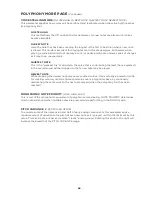
Page 54: ...Outputs MAIN SYNTH 2 OFF ON Setting this parameter to On will route Synth 2 to the MAIN L and MAIN R Outputs MAIN SYNTH 3 OFF ON Setting this parameter to On will route Synth 3 to the MAIN L and MAIN R Outputs SUB SYNTH 1 OFF ON Setting this parameter to On will route Synth 1 to the SUB L and SUB R Outputs on the Rear Panel SUB SYNTH 2 OFF ON Setting this parameter to On will route Synth 2 to the ...

Page 55: ...NSERT 3 buss INSERT 4 SYNTH 1 OFF ON Setting this parameter to On will route Synth 1 to the INSERT 4 buss INSERT 4 SYNTH 2 OFF ON Setting this parameter to On will route Synth 2 to the INSERT 4 buss INSERT 4 SYNTH 3 OFF ON Setting this parameter to On will route Synth 3 to the INSERT 4 buss INSERT 4 EXT XLR OFF ON Setting this parameter to On will route an audio signal arriving at the EXT INPUT XL...

Page 56: ...erge the return signal to the MAIN R bus In this way a monaural signal sent to an external processor can return in stereo using a pair of adjacent insert points 1 2 or 3 4 So the monaural signal sent via INSERT 1 can be returned in stereo using INSERT 1 and INSERT 2 Further these adjacent pairs are normalled so that if nothing is connected to INSERT 2 the monaural return signal arriving at INSERT ...

Page 57: ...ect Moog One to recall a specific Preset from memory TIP The active BANK A H and PRESET 1 8 buttons will light at full intensity unselected PRESET buttons will have a softer light If a PRESET button appears dark unlit then no Preset has been assigned to that location Performance Sets are stored by number This provides a consistent order when browsing Performance Sets and also facilitates remote MI...

Page 58: ...he other Presets in that Bank will be re numbered accordingly NOTE If a Preset not assigned to the current Performance Set was active before pressing the MORE button then Bank A of the current Performance Set will be selected but no Preset will be highlighted The first time you turn the Master Encoder Preset 1 of the active Performance Set will be selected After that the Master Encoder will load P...

Page 59: ...mance Set is placed between existing Performance Sets no data is overwritten DELETING A PERFORMANCE SET Once a Performance Set is highlighted pressing the DELETE button on the Front Panel will delete it The other performance sets will move to fill the gap ADDING A PERFORMANCE SET Use the Master Encoder to scroll to the bottom of the Performance Set list until the indicator appears Highlight this i...

Page 60: ...he character to the left of the cursor Keys C 5 and D 5 respectively change the character immediately preceding the cursor to the previous or next symbol in the current character set changing an M to an L or an N for example with a single key press Keys F 5 and G 5 move the cursor left or right respectively Key A 5 adds a space NOTE The note numbers given above relate to the onscreen keyboard and ...

Page 61: ... One advantage of using Sync is that by changing just the Master Clock Rate all of the sync d parameters will also change and will remain in step with the Master Clock NOTE The current tempo is always displayed in the HOME screen TEMPO 0 to 10 This knob sets the tempo for the Master Clock Turn the TEMPO knob to the left to slow down the Master Clock turn the TEMPO knob to the right to speed up the...

Page 62: ...uch time the on beat occupies relative to the total duration of an on beat plus an off beat Below the tempo value is a type of bar graph showing the amount of Swing being applied In this bar graph each white box represents an on beat and each grey box represents the complementary off beat As you rotate the Soft Knob to change the amount of Swing the relationship between these two boxes will change...

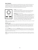
Page 63: ...ry little effort but it also can quickly chew up polyphony Remember that with the Moog One three oscillator architecture you can also set up the Oscillators tunings to play a major triad on each key while using only a single voice That said there are many situations where the CHORD function is the way to go In the Moog One architecture the CHORD function is the last module to be presented with not...

Page 64: ...tacked voices Adding a second note will reallocate four voices to a Unison stack on the new note and four voices will continue to play in a Unison stack on the already held note etc NOTE Use the UNISON COUNT parameter in the Polyphony MORE page to limit and specify the number of voices being stacked per note DETUNE 0 to 10 When the UNISON button is On Lit rotating this knob to the right will apply...

Page 65: ...ow of parameters Rotating the Master Encoder to the left will select a previous row Again rotate the Soft Knob below the parameter to change its value UNISON COUNT MINIMUM 2 MAXIMUM POLY COUNT VALUE The number of voices allocated here will determine the depth and fatness of the Unison effect The minimum number of voices is 2 the maximum limit is the number of voices set by the POLY COUNT parameter...

Page 66: ...test in the overall sound will be dropped so that a new note may be played NEWEST NOTE While dropping the newest note may seem counterintuitive this is actually a powerful mode for creating mono synth style figures and solos over a polyphonic base by continually reallocating the same voice to the next note played when the polyphony limit has been reached MONOPHONIC NOTE PRIORITY LOW HIGH LAST This...

Page 67: ...uld in no way be seen as limiting to the user any of these modulation sources and destinations can be connected in new and different ways using the expansive Modulation Matrix HARD WIRED OSCILLATOR COMMON MODULATION PARAMETERS Here the Pitch Modulation and Waveform Modulation parameters are applied to all Oscillators equally Selecting the Ring Modulation sources and choosing a Frequency Modulation...

Page 68: ...c modulation destination Once a DEST or an EXPRESSION ASSIGN button has been pressed the Quick Assign modulation screen will open in the Center Console In this example LFO 1 was the chosen as the modulation source The destination will be assigned automatically to the first hardware parameter that is touched or operated In this example Oscillator 2 Frequency has been chosen as the modulation destin...

Page 69: ...on paths that have the same source as this newly created path again in this case LFO 1 Navigating inside the Modulation Matrix is covered extensively in the next section ADD DESTINATION Pressing the ADD DESTINATION Soft Button saves the current modulation same as the DONE button and returns to the initial Quick Assign screen where an additional destination for the same modulation source may be cho...

Page 70: ...t Knobs to edit an existing value To create a new path inside the Modulation Matrix rotate the Master Encoder to select the first available empty unassigned slot Use the Soft Knobs to assign a source destination etc to the new modulation path In either case press down on the Master Encoder to toggle between top row and bottom row parameters TIP As an aid to programming the far left Soft Button act...

Page 71: ...m in the modulation path offers a number of ways to manipulate the value of the modulation signal as it travels from the source to the destination The Transform is selected using the top parameter row the value is entered using the bottom row parameters NONE This is the default setting no transform has been applied to the modulation path LIMIT LOW 0 to 100 This Transform artificially sets a lower ...

Page 72: ...e Modulation Matrix list TIP Notice that when modulation paths appear in the filtered list they retain their existing slot numbers which can also make it easy to find and reference them in the future FILTERING BY SOURCE Holding the SHIFT button while pressing any one of the DEST buttons on the Front Panel LFOs EGs will open the Modulation Matrix but showing only the modulation paths using that mod...

Page 73: ...e Gerry created during the studio session etc Press the NOTES Soft Button and follow the screen prompts After naming the Modulation Matrix and adding any notes press the OK Soft Button to save the Modulation Matrix or press the CANCEL Soft Button to exit the Modulation Matrix SAVE screen without saving ENTERING TEXT Moog One allows you to enter names and text directly from the keyboard The white k...

Page 74: ...ace the performance notes saved with this Modulation Matrix preset In this case the Modulation Matrix is never loaded but the notes text metadata is updated When you are done editing the notes press the OK Soft Button to save the changes or the CANCEL Soft Button to exit without saving LOAD ADD Rotate the Master Encoder to choose a Modulation Matrix preset from the list Pressing the LOAD ADD Soft ...

Page 75: ... LFO 3 PAD X SQUARED LFO 4 PAD Y CUBED FILTER EG PAD PRESSURE AMPLIFIER EG PAD GATE MODULATION EG VELOCITY NOISE EG AFTERTOUCH MOD WHEEL KEY PITCH PITCH WHEEL KB GATE PAD X SUSTAIN PAD Y EXP 1 PAD PRESSURE EXP 2 PAD GATE CV IN 1 VELOCITY CV IN 2 AFTERTOUCH FILTER EG KEY PITCH AMPLIFIER EG KB GATE MODULATION EG SUSTAIN NOISE EG EXP 1 LFO 1 EXP 2 LFO 2 CV IN 1 LFO 3 CV IN 2 LFO 4 RANDOM RANDOM RANDO...

Page 76: ... DELAY SAW NOISE LEVEL ATTACK TRIANGLE EXT LEVEL HOLD PULSE VCA DECAY MIX LEVEL SUSTAIN OSCILLATOR 2 PAN RELEASE FREQUENCY FILTERS TIME SCALE BEAT SVF LADDER MIX EG 3 SAW SVF FILTER DELAY TRIANGLE CUTOFF ATTACK PULSE RESONANCE HOLD MIX SPACING DECAY OSCILLATOR 3 EG AMOUNT SUSTAIN FREQUENCY LFO 2 AMOUNT RELEASE BEAT FM AMOUNT TIME SCALE SAW LADDER FILTER TRIANGLE CUTOFF PULSE RESONANCE MIX EG AMOUN...

Page 77: ... SEMITONES RATE SEMITONES VARIATION VARIATION VARIATION DELAY DELAY DELAY FADE IN TIME FADE IN TIME FADE IN TIME FADE OUT TIME FADE OUT TIME FADE OUT TIME LFO 2 RATE RATE SEMITONES VARIATION DELAY FADE IN TIME FADE OUT TIME MODULATION Continued DESTINATIONS ...

Page 78: ...is always musically related to the performance ON ON LIT OFF UNLIT This button turns the Arpeggiator of the active Synth On and Off RATE 0 to 10 The RATE knob sets the speed of the Arpeggiator The actual tempo value ranges from 10 BPM to 280 BPM The Arpeggiator Rate can run at an independent speed or it can be synchronized to the Master Clock using the parameters accessed in the Arpeggiator MORE p...

Page 79: ... or lower than the original Press the OCTAVE button to cycle through the list of values the corresponding LED will light The minimum value is 1 which plays the pattern in its original octave the maximum value is 4 which plays the pattern in its original octave then an octave higher lower then two octaves higher lower and then three octaves higher lower The choice between higher and lower is made u...

Page 80: ... accessed and modified using the interactive portion of the Center Console These additional parameters are displayed in the bottom portion of the screen The right pane shows the current value of the Front Panel hardware parameters for this module Tweaking these panel controls will update their values here NOTE Pressing the now illuminated MORE button will exit the MORE page and recall the HOME scr...

Page 81: ...ues will be more flowing and legato FOLLOW SWING OFF ON The Master Clock includes parameters related to adding swing to the beat When sync d to the Master Clock the Arpeggiator can either follow this swing information or ignore it and play strictly to the BPM setting NOTE RESET OFF ON This parameter specifies how the timing of the Arpeggiator will behave when a new note is played on the keyboard W...

Page 82: ...he Master Clock tempo along with the LFOs EGs and the Arpeggiator to create a forceful rhythmic performance Each sequence can be saved as an individual entity or as part of the active Synth Preset ON ON LIT OFF UNLIT This ON button turns the Sequencer of the active Synth On and Off Turning the Sequencer On will not begin the playback of an existing sequence or the recording of a new one Instead th...

Page 83: ...ect more than one Synth and then press the u START STOP button RECORD RECORDING LIT NOT RECORDING UNLIT Pressing the O RECORD button places the sequencer in the Record mode Press the O RECORD button a second time to exit the Record mode ADV ADVANCE STEP BACK STEP FORWARD These buttons are used to select the current sequence step The current playback step is indicated by the CURRENT PAGE and ACTIVE...

Page 84: ...ak a knob entering a new value offset for each step As long as the STEP MOD button is lit you can continue to enter modulation values for multiple parameters just by rotating the corresponding knob Finally turn the Step Mod function Off by pressing the STEP MOD button a second time Once entered this data can be accessed and edited using the Step Edit feature NOTE The Sequencer does not need to be ...

Page 85: ...ing more lanes allows more notes to be assigned to each step Each Sequence can be up to 64 steps in length which is shown on the Step Edit screen and indicated on the Front Panel as four pages of sixteen steps each The exact number of steps is determined by the LENGTH parameter in the Sequencer MORE page BEGINNING WITH AN EMPTY SEQUENCE The active Synth may or may not already have data stored in t...

Page 86: ...or Down between rows Lanes You can also navigate up and down by turning the Master Encoder while SHIFT is active Each lane can only support one note per step so adding more lanes is required to have multiple notes on each step Pressing the ROW DOWN Soft button is one way to add an additional lane You can also simply play multiple notes on a single step Moog One will create a new lane for each addi...

Page 87: ...ound engine and the corresponding MIDI output to play the following step using the same voice as in a legato fashion without retriggering the EGs etc RESTS Entering a Rest places a silent step into the sequence The Step Indicator for this step will be shaded TIP A Rest step can be empty or it may contain Note value s This allows the Note s to be restored by removing the Rest status of the step RAT...

Page 88: ...e of the Note assigned to a specific lane of particular step RATCHET 1 to 4 Ratcheting allows the Sequencer to re articulate a note multiple times inside of a single step a sort of sequence stutter mode This is an excellent tool for creating multiple triggers of the same note without using up multiple steps The Ratchet Soft Knob at the bottom of the screen is used to control the number of Ratchets...

Page 89: ...Step Mod function to record the changing value of a particular parameter as the Sequencer is running either while recording or playing back With the sequence stopped the Step Mod method can be used to quickly edit modulation values in the STEP EDIT page If it is not already open press the STEP EDIT button to open the MODULATION SEQUENCE page Press the MODULATIONS Soft Button at the top of the scre...

Page 90: ...oft knob to set the OFFSET amount for each sequence step Press the ROW DOWN Soft button and then press down on the MASTER ENCODER to create a new Modulation lane Repeat the same procedure for assigning a modulation destination to your Modulation routing lane and for setting the offset values for each step EDITING MODULATION DATA The CONTROLLER AMOUNT CATEGORY and DESTINATION of each modulation lan...

Page 91: ...D SPACING PULSE LFO 3 MOD EG AMOUNT FM AMOUNT LFO 2 AMOUNT OSC 1 2 3 FM AMOUNT OCTAVE LADDER FILTER FREQUENCY CUTOFF BEAT RESONANCE SAW EG AMOUNT TRIANGLE LFO 2 AMOUNT PULSE FM AMOUNT MIX EG 1 2 3 NOISE DELAY COLOR MIX ATTACK ATTACK HOLD SUSTAIN DECAY RELEASE SUSTAIN VCA RELEASE LEVEL MULTI TRIGGER PAN SYNC FILTERS LOOP SVF LADDER MIX LATCH LFO 1 2 3 4 RATE WAVEFORM VARIATION DELAY RAMP UP TIME RA...

Page 92: ...ge its value SYNC OFF ON When Sync is Off the Sequencer is free to run at its own tempo When Sync is On the Sequencer and Master Clock are synchronized and the Master Clock determines the Sequencer tempo NOTE When SYNC ON is selected here rotating the Sequencer RATE knob on the Front Panel will select quantized clock divisions see below of the Master Clock CLOCK DIVISION 4 2 1 1 2 1 4 1 8 1 16 1 3...

Page 93: ...parameter is off and the HOLD NOTE TRIG and TRANSPOSE buttons from the Sequencer module area all set to On then playing a new note while a previous note is still held will transpose the sequence without resetting back to step one RESTART ON TRIG OFF ON This RESTART ON TRIG Restart On Note Trigger parameter specifies how the timing of the Sequencer will behave when the NOTE TRIG button in the Seque...

Page 94: ...n be used to create a single sequence that will play all the parts of a split or layered sound LOADING A SEQUENCE Pressing the LOAD Soft Button at the top of the screen will open the Load Sequence screen The left pane will show a list of all of the available Sequences To make it easier to locate a saved Sequence this list can be sorted by name by pressing the SORT BY NAME Soft Button at the top of...

Page 95: ...he cursor to the previous or next symbol in the current character set changing an M to an L or an N for example with a single key press Keys F 5 and G 5 move the cursor left or right respectively Key A 5 adds a space NOTE The note numbers given above relate to the onscreen keyboard and do not reflect the key s actual MIDI Note number etc TIP You can also enter names directly using a standard USB k...

Page 96: ...to be tweaked parameters in each Effect but they can be easily re assigned to any available parameter by using the EFFECT TYPE page The status of the ON button and the value of the CTRL 1 and CTRL 2 knobs are saved as part of the Timbre SYNTH EFFECT STRUCTURE Synth Effects are classified by type Delay Chorus Flanger etc Once a particular type of effect has been selected and loaded the individual p...

Page 97: ...once again on the Master Encoder to load the Effect A white vertical bar will appear before the Effect name to indicate the Effect has been loaded Press the BACK Soft Button at the top of the screen to return the cursor to the left pane to select a different Effect Type To load an initialized Effect Type use the Master Encoder to select an Effect Type and press the LOAD Soft Button to call up a de...

Page 98: ...ision values of the Master Clock tempo SAVING AN EDITED EFFECT Once you have made all of your edits to the Effect press the SAVE Soft Button at the top of the screen Here you can name your edited Effect ENTERING TEXT Moog One allows you to enter names and text directly from the keyboard The white keys naturals enter the characters certain black keys accidentals have specific functions Keys C 1 D 2...

Page 99: ...d as a modulation destination using the Modulation Matrix allowing the panning of individual voices as they are played this per voice panning cannot be preserved in the dual mono buss feeding the Master Effects The per voice panning will continue to affect the Dry unprocessed signal but the Wet processed signal will rely on the Synth pan position as determined by the VCA MORE page settings However...

Page 100: ...d a stereo output STEREO WIDTH 0 to 100 to 200 The algorithm controlled by this parameter determines the width of the stereo image created by the Master Effects At the 0 setting the stereo image is in fact monaural Rotating the Soft Knob to the left will increase the value of this parameter At 100 the default stereo image is restored Increasing the value even further enhances the stereo effect up ...

Page 101: ...down on the Master Encoder CHANGING EDITING THE MASTER EFFECT PARAMETER VALUES Press the EFFECT 1 PARAMS or EFFECT 2 PARAMS Effect Parameters Soft Button at the top of the screen The left pane shows a graphic image of the components that make up the active Master Effect The right pane shows the value of the SEND 1 or SEND 2 knob for each of the three Synths The bottom portion of the screen shows a...

Page 102: ...e character set Key F 4 removes the current name and randomly generates a new name Key G 4 clears all the characters in the screen Key A 4 deletes the character to the left of the cursor Keys C 5 and D 5 respectively change the character immediately preceding the cursor to the previous or next symbol in the current character set changing an M to an L or an N for example with a single key press Key...

Page 103: ...103 This page left intentionally blank ...

Page 104: ...o 100 TIME DELAY TIME 0 1ms to 2000ms CTRL 2 GAIN GAIN STAGE OF THE PROCESSED SIGNAL 0 to 100 SYNC SYNC ON OR OFF ON OFF PARAMETER NAME PARAMETER DESCRIPTION RANGE ASSIGNED MIX AMOUNT OF DELAY SIGNAL IN THE OUTPUT 0 to 100 CTRL 1 FEEDBACK DELAY SIGNAL FED BACK TO THE INPUT 0 to 100 CTRL 2 TIME LEFT DELAY TIME FOR THE LEFT SIDE 0 1ms to 2000ms TIME RIGHT DELAY TIME FOR THE RIGHT SIDE 0 1ms to 2000m...

Page 105: ... NOISE 0 to 100 TONE LPF TONE CONTROL 0 to 100 MOD AMOUNT OF RANDOMNESS MODULATION IN THE DELAY LINE 0 to 100 GAIN GAIN STAGE OF THE PROCESSED SIGNAL 0 to 100 SYNC SYNC ON OR OFF ON OFF PING PONG Dual Tap Digital Delay Line Cubically Interpolated with Alternating Stereo Spatialization BBD DELAY Single Tap Digital Delay BBD Bucket Brigade Delay Emulation MIX AMOUNT OF DELAY SIGNAL IN THE OUTPUT 0 t...

Page 106: ...LFO RATE OF MODULATION 0 1Hz to 10Hz CTRL 1 DEPTH LFO DEPTH OF MODULATION 0 to 100 CTRL 2 TONE LPF CUTOFF CONTROL 0 to 100 NOISE AMOUNT OF NOISE IN SIGNAL 0 to 100 SPREAD STEREO SPREAD AMOUNT 0 to 100 GAIN GAIN STAGE OF THE PROCESSED SIGNAL 0 to 100 SYNC SYNC ON OR OFF ON OFF MIX AMOUNT OF CHORUS SIGNAL IN THE OUTPUT 0 to 100 FEEDBACK CHORUS SIGNAL FED BACK TO THE INPUT 100 to 100 TIME CHORUS TIME...

Page 107: ...AL 0 to 100 SYNC SYNC ON OR OFF ON OFF MIX AMOUNT OF CHORUS SIGNAL IN THE OUTPUT 0 to 100 CTRL 1 FEEDBACK CHORUS SIGNAL FED BACK TO THE INPUT 0 to 100 CTRL 2 TIME CHORUS TIME 3ms to 60ms RATE LFO RATE OF MODULATION LOW MED HIGH DEPTH LFO MODULATION DEPTH 0 to 100 TONE LPF CUTOFF CONTROL 0 to 100 VIBRATO RATE RATE OF VIBRATO 0 1Hz to 10Hz VIBRATO DEPTH DEPTH OF VIBRATO 0 to 100 SPREAD STEREO SPREAD...

Page 108: ...NS HIGH FREQUENCY INTENSITY 0 to 100 NOISE NOISE AMOUNT 0 to 100 GAIN GAIN STAGE OF THE PROCESSED SIGNAL 0 to 100 SYNC SYNC ON OR OFF ON OFF MIX AMOUNT OF PHASER SIGNAL IN THE OUTPUT 0 to 100 CTRL 1 PHASER FEEDBACK PHASER FEEDBACK EMULATION 0 to 100 SWEEP PHASER ZERO POINT 0 to 100 RATE LFO RATE OF MODULATION 0 01Hz to 20 Hz DEPTH LFO DEPTH OF MODULATION 0 to 100 TONE LPF CUTOFF ON MIXED SIGNAL DA...

Page 109: ...D RATE RATE OF MODULATION 0 01Hz to 10Hz MOD DEPTH DEPTH OF MODULATION 0 to 100 GAIN GAIN STAGE OF THE PROCESSED SIGNAL 0 to 100 MIX AMOUNT OF VOCODER SIGNAL IN THE OUTPUT 0 to 100 CTRL 1 SIBILANCE AMOUNT OF SIBILANCE SIGNAL MIXED INTO THE OUTPUT 0 to 100 SENSITIVITY GATE SENSITIVITY CONTROL FOR THE MIC INPUT 0 to 100 CTRL 2 TONE HPF OF SIBILANCE NOISE SIGNAL 0 to 100 NOISE MIX BETWEEN INPUT SIBIL...

Page 110: ... 0 85 INFINITE FREEZE 1 REFLECTION DENSITY SPREAD AND TIME MACRO FOR EARLY REFLECTION DELAY TAP NETWORK THIS EFFECT HAS 20 DETENTS AS FOLLOWS EARLY 10 LATE 0 0 EARLY 10 LATE 1 0 05 EARLY 10 LATE 10 0 5 EARLY 9 LATE 10 0 55 EARLY 0 LATE 10 1 DIFFUSION FEEDBACK COEFFICIENT FOR EARLY REFLECTION LOOP 0 100 MOD LEVEL MODULATION DEPTH OF DELAY TAP IN EARLY REFLECTIONS 0 100 HIGH FREQ CUTOFF FOR LPF PRES...

Page 111: ...EIVED SIZE OF THE REVERBERANT SPACE 0 100 DECAY OVERALL DECAY FOR THE ENTIRE REVERB FEEDBACK PATH 0 100 DISTANCE DELAY TIME FOR EARLY REFLECTION TAP NETWORK 0 100 DIFFUSION FEEDBACK COEFFICIENT FOR EARLY REFLECTION NETWORK 0 100 MOD LEVEL MODULATION DEPTH OF DELAY TAP IN EARLY REFLECTIONS 0 100 TONE CUTOFF FOR LPF AT INPUT 100 100 HIGH DAMP GAIN COEFFICIENT INSIDE HIGH ALL PASS RING TANK 100 0 LOW...

Page 112: ...ITE FREEZE 1 RESONANCE RESONANCE PEAKS IN RESONANT BIQUAD CROSSOVER 0 100 HIGH LEVEL GAIN COEFFICIENT POST HIGH ALL PASS RING TANK 100 100 LOW LEVEL GAIN COEFFICIENT POST LOW ALL PASS RING TANK 100 100 PRE DELAY PRE DELAY TIME BEFORE THE REVER TAIL BEGINS 0 2000ms SIZE PERCEIVED SIZE OF THE REVERBERANT SPACE 0 100 GRAVITY SOME SORT OF BLOOM OR GAIN FEEDBACK COEFFICIENT 100 100 EVENTIDE BLACKHOLE M...

Page 113: ...113 This page left intentionally blank ...

Page 114: ...of the keyboard will now play the note C3 MIDI Note 48 where the same key at the default octave setting previously played C5 MIDI Note 72 This ability to Octave Shift matches the playing area to the performance without the need to reprogram the sound and Oscillator settings NOTE Press and hold both OCTAVE buttons to send a MIDI Panic All Notes and Controllers Off message GLIDE ON LIT OFF UNLIT Ins...

Page 115: ...s found in the individual Oscillator MORE pages allowing for exacting control MOD WHEEL Use the MOD wheel to manually articulate the amount of modulation being applied in one or multiple instances Unlike the PITCH wheel the MOD wheel is not spring loaded and its starting position can be saved as part of the Preset NOTE Moog One is equipped with an aluminum MOD wheel that has been purposefully desi...

Page 116: ...and a friend to both listen to Moog One without any external amplifiers LHC MORE PAGE Pressing the triangular MORE button in the upper right corner of the Left Hand Controller will reveal a second level of parameters that can be accessed and modified using the interactive portion of the Center Console These additional parameters are displayed in the bottom portion of the screen The left pane shows...

Page 117: ...ves two octaves up and two octaves down in semitone units With a value of zero the PITCH wheel will have no effect when moved up NOTE Holding the SHIFT button while operating the Pitch Bend Up Soft Knob will allow a finer resolution than semitone units when setting the value PITCH BEND DOWN 24 to 0 to 24 The change in pitch caused by moving the PITCH wheel down can be specified here Negative value...

Page 118: ... loud notes a touch louder and soft notes a touch softer providing a broader dynamic range than would otherwise be achieved GATED GLIDE OFF ON This is a special case for using Glide When On the keyboard acts as a gate that will pause and resume the glide effect as the key s is played LEGATO GLIDE OFF ON Again a special case for articulating the Glide effect In this case Glide is produced only when...

Page 119: ...nd reloaded as part of the Synth PAD The held position of the X Y PAD is saved and reloaded as part of the Synth BOTH The position of the MOD wheel and the held position of the X Y PAD are both saved and reloaded as part of the Synth SEMITONE TRANSP 12 to OFF to 12 The overall pitch of the active Synth may be transposed up or down up to one octave in semitone units Layered Synths can be pitched a ...

Page 120: ...P These tags make it easy to search for Presets by narrowing the list While all of the tag types come with some preloaded suggestions the user is free to create their own CATEGORY MOOD and GROUP divisions Only TYPE has fixed options SINGLE LAYER SPLIT and MULTI Generally one would use SINGLE for a Preset using a single Synth SPLIT for multiple Synths playing in different areas of the keyboard LAYE...

Page 121: ...OAD PRESET Soft Button at the top of the screen to load the selected and highlighted Preset TIP When the PRESET AUTOLOAD function SETTINGS GLOBAL HARDWARE SETTINGS is set to On scrolling from one entry to the next in the Browser will load the selected Preset automatically without the need to Press down on the Master Encoder or to use the LOAD PRESET Soft Button TIP Loading a Preset will load up to...

Page 122: ...ton at the top of the screen Preset names must be unique if the name you have entered is already in use a popup box will ask if you want to overwrite the Preset of the same name Press the YES Soft Button to overwrite the existing Preset press the NO Soft Button to return to previous screen and edit the name Then you can press the SAVE AS Soft Button again and save the Preset under the new name ADD...

Page 123: ...e discoverable in a search Rotate the Soft Knobs to select a value for each search criteria While all of the criteria come with some preloaded suggestions each performer is free to create their own CATEGORY MOOD and GROUP divisions Only TYPE has fixed options SINGLE LAYER SPLIT and MULTI Generally individual Timbres default to Single When the tags have been added use the SAVE TIMBRE X Soft Button ...

Page 124: ...ime pressing the COMPARE button so that it is lit will allow to hear the original version Loading a different Preset will clear both the Edit and Compare buffers SNAPSHOT As you are editing Moog One enables multiple Snapshots to be taken Each Snapshot is a micro save of the current Preset In this way you can save your edits as you go along without having to worry about an all or nothing scenario w...

Page 125: ...nected to the Moog One USB HOST port Once you have loaded a Snapshot you can use the SAVE menu SAVE PRESET Soft Button operation to overwrite the Preset using this version Any performance notes saved to that Snapshot will now be saved with the Preset and all the other Snapshots will remain in the Snapshot file Or you can choose to save the recalled Snapshot as its own separate Preset by assigning ...

Page 126: ...ssing down on the Master Encoder will move the red colored cursor to the right pane where an individual parameter may be selected and highlighted by rotating the Master Encoder The Settings Category will remain highlighted in gray Values for the specific parameter selected in this right pane are controlled using the Soft Knobs s at the bottom of the screen TIP When the cursor is located on the rig...

Page 127: ...127 This page left intentionally blank ...

Page 128: ...utton can be done audibly so you can hear the notes as they are entered or silently so that the audience doesn t hear you loading the chord in a performance situation SILENT LEARN In this mode the output of the active Synth is muted while the LEARN button is engaged allowing the chord to be learned discreetly AUDIBLE LEARN In this mode the output of the active Synth is unaffected by the LEARN butt...

Page 129: ...RE When this value is selected items with identical names will not be exported OVERWRITE When this value is selected the item being exported will replace the item of the same name by rewriting the data AUTO RENAME When this value is selected the exported item will be given a new name by adding a COPY 1 to the end of the name and then saved to the external device If COPY 1 has already been used COP...

Page 130: ...y if the 24 hour clock is chosen the AM PM option listed above will not be viewable DATE TIME FORMAT This parameter will determine how the current date and time are displayed Soft Knob 1 DATE FORMAT DD MM YYYY MM DD YYYY or YYYY MM DD Soft Knob 2 TIME FORMAT 12 HR or 24 HR CURRENT TIME The current Moog One TIME and DATE set are displayed here FAN MODE Inside your Moog One variable speed fans work ...

Page 131: ...OL parameters define how Moog One will communicate with other devices and determine what types of MIDI data is being shared Use the Master Encoder to scroll through the parameters and use the Soft Knobs at the bottom of the screen to set the value RECEIVE MIDI CLOCK OFF ON When this parameter is set to On Moog One will receive timing and tempo information from an external MIDI source overriding th...

Page 132: ...ue is set to PER SYNTH then each Synth in the current Preset can receive MIDI data on an independent MIDI Channel by setting each of the MIDI IN CHANNEL SYNTH 1 MIDI IN CHANNEL 2 and MIDI IN CHANNEL SYNTH 3 parameters that will be present and available MIDI IN ROUTE ALL SYNTHS SELECTED MIDI IN CHANNEL ALL OFF 1 to 16 This parameter selects the MIDI Channel that all of the Synths in the current Pre...

Page 133: ... OUT CHANNEL 2 and MIDI OUT CHANNEL SYNTH 3 parameters that will be present and available MIDI OUT ROUTE ALL SYNTHS SELECTED MIDI OUT CHANNEL ALL OFF 1 to 16 This parameter selects the MIDI Channel that all of the Synths in the current Preset will use to transmit data MIDI OUT ROUTE PER SYNTH SELECTED MIDI OUT CHANNEL SYNTH 1 OFF 1 to 16 This parameter selects the MIDI Channel that Synth 1 will us...

Page 134: ...RS The parameters listed below are identical for every CV INPUT however they are set individually using a repeating format for each CV INPUT FUNCTION This parameter selects the function destination of the incoming control voltage signal arriving at the chosen jack CV INPUT DESTINATIONS SUSTAIN IN This feature is used to determine how Moog One will react to varying types of sustain pedal FUNCTION O...

Page 135: ...sic com register to receive the latest firmware updates as they become available Moog One is equipped with four 1 4 Control Voltage CV Outputs on the rear panel CV OUT 1 CV OUT 2 CV OUT 3 and CV OUT 4 All of these outputs can be configured to work with a variety of CV destinations from other modular and Eurorack synthesizers to standalone CV synthesizers LOAD FROM PRESET OFF ON The CV OUTPUT setti...

Page 136: ...rom time to time it may be necessary to update your Moog One firmware as its operations are improved and performance is enhanced The update data file can be downloaded from the Moog web site and saved to a USB thumb drive the drive must be formatted in a FAT format The update file should be saved to the root directory of the USB drive meaning not placed inside another folder Insert the drive into ...

Page 137: ...ating the Master Encoder The Library Category will remain highlighted in gray UNDERSTANDING THE USER SPACE The User Space is the current Moog One working environment All of the Global settings all of the Presets Synths Modulation Matrices Sequences Effect settings and more exist within the confines of the User Space The good news is that multiple User Spaces can be created saved and recalled eithe...

Page 138: ...and G 5 move the cursor left or right respectively Key A 5 adds a space EDITING A USER SPACE Rotate the Master Encoder to highlight and select a User Space from the list in the right pane the Active User Space cannot be edited Pressing the MASTER ENCODER will open a new screen where you can rename the selected User Space using the keyboard entry method At this point the Soft Buttons at the top of ...

Page 139: ...PRESS ENCODER TO TOGGLE SELECTION ON OFF NOTE If no external USB drive is present the screen prompt will read USB STORAGE DEVICE NOT DETECTED In addition to selecting items individually pressing the SELECT ALL Soft Button will select every item in the current list for export The SELECT NONE Soft Button will deselect any previously selected items Once you have made your selection s press the EXPORT...

Page 140: ...press the CANCEL Soft Button UNDERSTANDING CATEGORIES MOODS AND GROUPS Moog One allows the assigning of tags to each Preset and Synth as it is saved These tags can be applied as search criteria when using the BROWSER pages to find either a specific Preset or Synth or a suitable Preset or Synth based on these tags The tag Criteria are TYPE CATEGORY MOOD and GROUP Of these three are editable so that...

Page 141: ... new Mood you created will appear on the list To exit before creating the new Mood press the CANCEL Soft Button at the top of the screen To edit the name of an existing Mood rotate the Master Encoder to highlight the Mood from the list in the right pane Press the MASTER ENCODER to open a new screen where you can rename the Mood using the keyboard entry method Once you have completed renaming the M...

Page 142: ...eter controls the base frequency for equal tempered tuning of the Moog One This is the reference point for concert pitch defined as the frequency of the A note above Middle C MIDI Note 69 The default value is 440 Hz MASTER FINE TUNE 100 CENTS to 0 CENTS to 100 CENTS This parameter provides a global offset in pitch affecting the entire Moog One The range is 100 cents up or down one semitone This al...

Page 143: ... Series operation STATE VARIABLE Two 12dB per octave filters operating as one filter configurable as NOTCH BP LP and HP with 12dB or 24dB slopes Cutoff Resonance etc LADDER FILTER Moog Ladder Filter with HP or LP options and selectable filter slopes 6db 12db 18dB or 24dB Cutoff Resonance etc ENVELOPES x3 Delay Attack Hold Decay Sustain and Release variable curves per stage plus multi triggering lo...

Page 144: ...TRS balanced TS unbalanced compatible SUB OUTPUTS Sub 1 Sub 2 1 4 TRS balanced TS unbalanced compatible AUDIO INSERTS Insert 1 Insert 2 Insert 3 Insert 4 1 4 TRS Send Returns Can be used as TS monaural outs EXTERNAL MIC LINE INPUT XLR 1 4 TRS combo jack with trim knob EXTERNAL LINE INPUT 1 4 TRS TS compatible HEADPHONES 2x Stereo 1 4 jacks located on the front edge of the Left Hand Controller CONT...

Page 145: ...must be returned in the original inner packing including the cardboard inserts Sorry the warranty will not be honored if the product is not properly packed Once you have received the RMA and carefully packed your Moog ship the product to Moog Music Inc with transportation and insurance charges paid and include your return shipping address MOOG MUSIC 160 Broadway St Asheville NC 28801 WHAT WE WILL ...

Page 146: ...146 ...
Reviews: