E. FILTERS
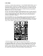
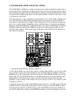
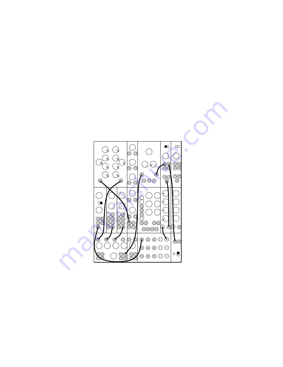
Four filters are included with the Synthesizer 15. The 907 FIXED FILTER BANK consists of
ten separate sections, each with its own attenuator. Eight of these sections cover frequency
bands approximately one-half octave each. The center frequencies are indicated by the large
numbers above the appropriate attenuator knobs. The remaining two pass the rest of the au-
dible spectrum: the LOWPASS section covers 20 to 200 Hz (cycles per second) while the
HIGHPASS section covers 3,500 to 20,000 Hz.
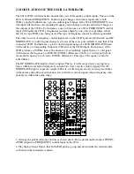
The 904A VOLTAGE CONTROLLED LOWPASS FILTER consists of a single lowpass fil-
ter section. The cutoff point is voltage controlled. That portion of the frequency spectrum be-
low the cutoff point is passed by the filter, while frequencies above the cutoff point are at-
tenuated. The REGENERATION control controls the amount by which the frequencies
around the cutoff point are emphasized.
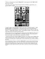
The 923 FILTERS provide a more subtle (6-dB per octave filter slope) alteration of the fre-
quency spectrum of a signal. The 923 LOWPASS FILTER passes that portion of the fre-
quency spectrum below the cutoff point. The 923 HIGHPASS FILTER passes that portion of
the frequency spectrum above the cutoff point. In each case, the cutoff point is set manually
using a control calibrated in Hertz (frequency in cycles per second).
995
904A
902
902
921A
921B
923
921
911
911
921B
MIXER
REV
CONTROLLERS
TRUNK
907A
0
0
8’
50
6
0
16’
A
B
C
6
2
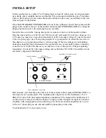
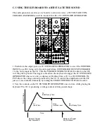
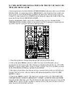
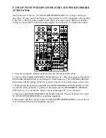
1. Clear the instrument. Arrange all patchcords and controls as indicated.
2. Turn up the MIXER control A. White noise should be heard. Slowly turn controls of the
907 FIXED FILTER BANK to the off position, starting with HIGHPASS and moving back
to LOWPASS. Next turn one section on, then off. Do this for all sections. Note that each
band has a sense of pitch that roughly corresponds to the band’s center frequency. For in-
stance, the 250 Hz section has an approximate apparent pitch of middle C. The sections can
be combined in any proportion by setting the front panel controls appropriately.


