background image

INITIAL SETUP

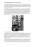
Set the synthesizer on a table 27 to 29 inches high, at least 24 inches deep. Avoid placement 
near drafts, direct sunlight, heaters and the like. For permanent installation, put a 5 inch plat-
form (or the keyboard cover) under the module cabinet to allow easy accessibility to the con-
trols and jacks at the bottom.

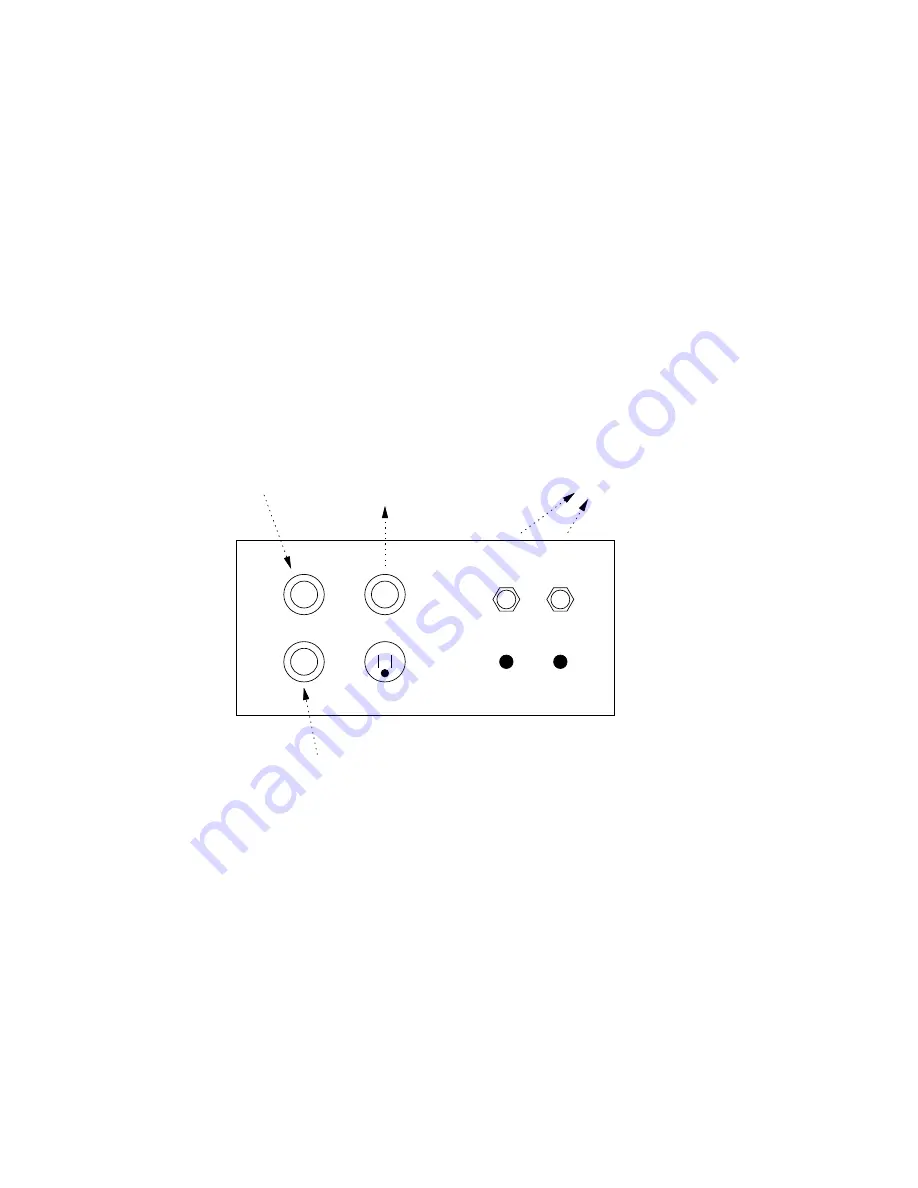
Place the KEYBOARD CONTROLLER in front of the synthesizer. Insert the keyboard cable 
plugs in the socket at the rear of the module cabinet marked CONTROLLER I & 2. Align the 
plugs properly and screw the retaining ring on carefully.

Insert the line cord in the 3-prong line power receptacle at the rear of the module cabinet. 
Plug the other end into a 110/130 volt, 50/60 cycle AC wall outlet. If your line voltage is over 
130 volts, you must use a step-down transformer of 60 volt-ampere rating. If your wall socket 
is the two prong type, use a three-prong adaptor. It is good practice to attach the free wire of 
the adaptor to a good ground such as a cold water pipe. If the line voltage in your building 
undergoes unusually large fluctuations, the synthesizer may occasionally produce a buzzing 
sound or waver in pitch. In this case, you may have to use a line power, voltage regulating 
transformer of at least 60 volt-ampere rating such as the Sola 20-13-060-2 (available at most 
electronic components distributors).

Controllers

1/2 A

1.5 A

Trunk Lines

1&2

3

From Wall Outlet

2

1

Slo-Blo

Line input

Amplifier or Tape Recorder

for additional cabinet

DC Power

From Keyboard

From Additional Controller

Run an audio cord from the jack at the rear of the module cabinet marked TRUNK LINE 1 to 
the input of your sound system. The nominal audio output level of the Synthesizer 15 is 0 
dBm (0-8 volt) at 600 ohm output impedance, unbalanced. The output of the Synthesizer 15 
can be directly connected to the line input of a tape recorder or high level input of a monitor 
amplifier with an appropriate interconnecting cord. For most monitor amplifiers use a cord 
with a 1/4" phone plug on one end and an RCA phone plug on the other.

Your Synthesizer 15 is now ready to use.

Summary of Contents for SYSTEM 15

Page 1: ...Instruction Manual for MOOG Synthesizer System 15 Introduction Module Functions Initial Setup Basic Definitions Instructional Sequences ...

Page 2: ...er operation Next you will explore the basic capabilities of the Synthesizer 15 through a sequence of illustrated in structions Once you acquire hands on familiarity with your instrument you will want to in crease your understanding of its more advanced capabilities by studying the module applica tion notes While on this tour you are always encouraged to experiment and devlop your own ways of usin...

Page 3: ...d pink sound for audio and control purposes 902 Voltage Controlled Amplifier Shapes the amplitude of a signal in response to any control signals 904A Voltage Controlled Lowpass Filter Attenuates that portion of the signal s frequency spectrum that lies above the cutoff fre quency Cutoff frequency responds to changes in control signals 907 Fixed Filter Bank Divides the audio spectrum into ten separ...

Page 4: ...ptor to a good ground such as a cold water pipe If the line voltage in your building undergoes unusually large fluctuations the synthesizer may occasionally produce a buzzing sound or waver in pitch In this case you may have to use a line power voltage regulating transformer of at least 60 volt ampere rating such as the Sola 20 13 060 2 available at most electronic components distributors Controll...

Page 5: ... JACK receives an audio signal for processing A CONTROL INPUT JACK receives a control signal for determining the operating point of a module A TRIGGER INPUT JACK is a two prong socket for accepting trigger signals MULTIPLE or MULT A group of interconnected jacks used for splitting a signal so it can be fed to more than one input MIXER An instrument for controlled combining of signals PATCH CORDS a...

Page 6: ...puts 3 Combine module outputs with a MIXER 4 Control signals may not be patched into the audio signal path However audio signals may be used as control signals 5 Patch only audio signals into signal input jacks Exception the 902 VOLTAGE CONTROLLED AMPLIFIER the 923 LOWPASS FILTER and the lower panel MIXER and REVERSIBLE ATTENUATOR are capable of processing slowly varying control signals ...

Page 7: ...d setting combinations After you begin to feel at home with the simpler patching and control setting procedures you will want to become familiar with the more sophisticated capabilities of each module The next section contains complete technical information on each of the modules A The Audio Generators B Using the Keyboard to Determine Pitch C Using the Keyboard to Articulate the Sound D Using Bot...

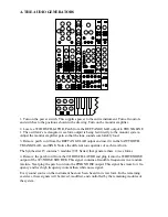
Page 8: ...emove patch cord from the RECTANGULAR output and insert it in the SAWTOOTH TRIANGULAR and SINE Notice the different tone qualities of each waveform The Synthesizer 15 contains 3 modules 921 Series that generate these 4 wave forms 4 Remove the patch cord from the 921B OSCILLATOR and plug it into the WHITE NOISE output of the 923 NOISE SOURCE This signal contains all audible frequencies in a random ...

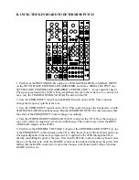
Page 9: ...quencies of both 921B OSCILLATORS simultaneously Flip the SEMITONE OCTAVE switch and note that the effect of the FREQUENCY control changes accordingly 4 Vary the WIDTH OF RECTANGULAR WAVE control on the 921A Note the change in tone color which accompanies waveform width change This control only affects the RECT ANGULAR outputs on the 921B s 5 Patch from the CONTROL VOLTAGE 1 output of the CONTROLL...

Page 10: ...FIXED CONTROL VOLTAGE control on the 902 to 0 Play the keyboard The trigger cable allows the keyboard to trigger the 911 ENVELOPE GENERATOR when ever a key is depressed Patching from a 911 to a 902 CONTROL IN PUT allows the voltage contour produced by the 911 to control the amplification of the 902 just as it was controlled manually by turning the FIXED CONTROL VOLTAGE control 2 Vary the controls ...

Page 11: ...e key is released the output voltage falls to zero with characteristic time T3 T1 T2 T3 and Esus are individually controllable by means of the 911 front panel controls Note that T1 and T2 apply only when a key is depressed and T3 is initiated upon releasing the key The articulated sounds that you hear have an envelope or loudness time contour that is the replica of the output signal of the 911 ...

Page 12: ...7A 0 0 8 50 6 0 16 A B C 1 Clear the instrument Arrange all patchcords and controls as shown above 2 Turn up the panel MIXER controls A and B Two tones should be heard one ap proximately an octave above the other Tuning is accomplished through the use of the FRE QUENCY controls and RANGE switches of either oscillator The two waveforms generated by the 921B OSCILLATORS are combined in the MIXER 3 P...

Page 13: ...S provide a more subtle 6 dB per octave filter slope alteration of the fre quency spectrum of a signal The 923 LOWPASS FILTER passes that portion of the fre quency spectrum below the cutoff point The 923 HIGHPASS FILTER passes that portion of the frequency spectrum above the cutoff point In each case the cutoff point is set manually using a control calibrated in Hertz frequency in cycles per secon...

Page 14: ... on the audio signal The FIXED CONTROL VOLTAGE determines the cutoff point of the filter REGENERATION empha sizes the cutoff point and RANGE determines the portion of the audio spectrum available for filtering 5 Turn down the FIXED CONTROL VOLTAGE of the 902 Play the keyboard The 902 is now articulating the tones Of course any of the filters can be used in conjunction with any of the audio signals...

Page 15: ...as shown above 2 Turn the 904A FIXED CONTROL VOLTAGE down to 3 Play the keyboard The left 911 ENVELOPE GENERATOR is controlling the cutoff frequency of the LOWPASS FILTER Experiment with the settings of the 911 to observe the effect of contour shape on tone color 3 While playing the keyboard gradually turn the REVERSIBLE ATTENUATOR to 0 No tice that the action of the 911 is pulled at 0 Gradually t...

Page 16: ...cillator Move the WAVEFORM selector switch through its posi tions Vary the LEVEL control The two outputs of this section are waveforms of variable levels The output presents an inversion of the wave just as the REVERSIBLE ATTENU ATOR does when in the position When the COARSE RANGE switch is in the SUB AUDIO position the 921 VOLTAGE CONTROLLED OSCILLATOR has a much lower frequency range most of whi...

Page 17: ...rn the 904A FIXED CONTROL VOLTAGE to 3 Turn REGENERATION to 6 The over tone content of the 921B waveform is now voltage controlled Return the FIXED CONTROL VOLTAGE to 6 8 Remove the plug from the 904A CONTROL INPUT and insert it in a 902 CONTROL IN PUT Turn the FIXED CONTROL VOLTAGE to 3 The amplitude of the 921B waveform is now voltage controlled In situations using voltage control the module s o...

Page 18: ...TROLLERS TRUNK 907A 0 50 8 0 0 8 50 R 10 1 Arrange the controls and patchcords as indicated 2 A sub audio sawtooth wave is controlling the frequency of the 921B waveform Set the CLAMPING POINT on 50 and strike keys at random time intervals With each new trigger the ramp will begin at the point designated by the CLAMPING POINT control Experiment with various clamping point settings and all controll...

Page 19: ... WEAK position When a 921B is not being synchronized the SYNCH switch should be in the center off position 995 904A 902 902 921A 921B 923 921 911 911 921B MIXER REV CONTROLLERS TRUNK 907A 0 0 8 A B C 1 Arrange all patchcords and controls as indicated 2 Tune the left 921B to an octave above the 921 and the right 921B to an octave plus a fifth above the 921 Listen to the beats produced by the mistun...

Page 20: ...he second subharmonic while the right 921B produces the third sub harmonic Listen carefully while varying the settings of the FREQUENCY and RANGE con trols on the 921B s You will hear the tones go in and out of synchronization ...

Page 21: ...t will result in a corresponding frequency difference at the 921B output For instance if the 921B produces a 1000 Hz tone in the absence of a modulating signal then a 1 volt signal will increase the frequency to 2000 Hz 1000 Hz difference while a 1 volt signal will de crease the frequency to zero also 1000 Hz difference This type of frequency control is called linear The DC MODULATE input is direc...

Page 22: ...n 6 Repeat the above step but with the patchcord plugged into the DC MODULATE input on the left 921B instead of the FREQUENCY control input on the 921A Note that the down ward interval jump is much greater than the upward interval JUMP 7 Move the patchcord from the DC MODULATE input on the 921B to the AC MODULATE input Notice that the effect of the square modulating wave on the pitch is radically ...

Page 23: ...put jacks are used However the inputs are arranged in a top to bottom hierarchy which permits a signal placed in the upper or middle input to appear at one or both lower inputs The follow ing diagrams illustrate using signals X and Y This allows simultaneous attenuation of up to three signals or capability of producing three different attenuations of a single signal 995 995 995 X X X X X Y X Y Y ...

Reviews: