background image

Polski – 

7

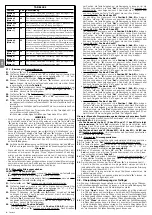
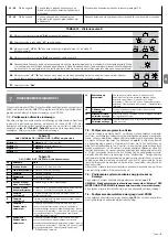
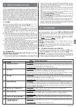
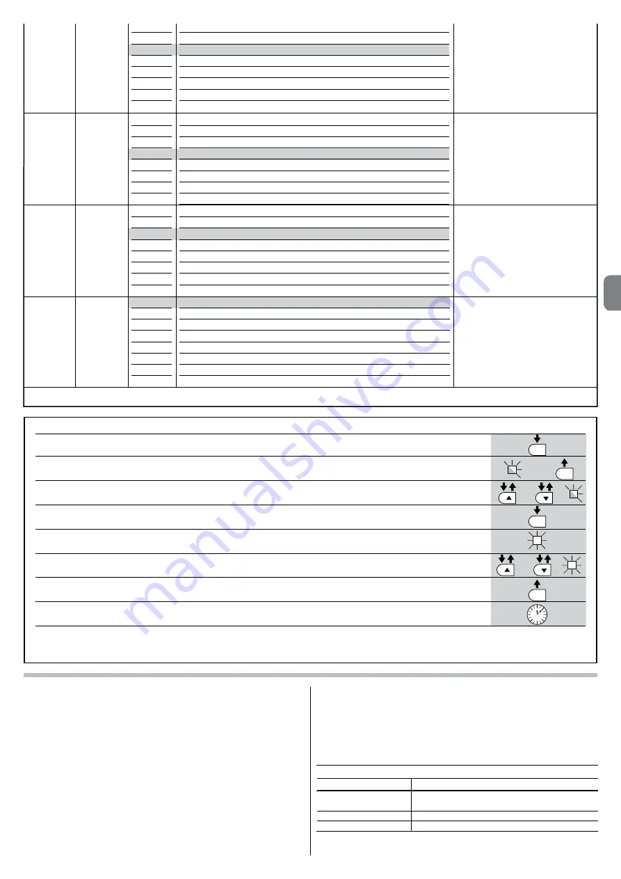
TABELA 7 - Procedura programowania drugiego poziomu

01.

  Wciśnij i przytrzymaj przycisk “

Set

” przez około 3 sekundy;

02.

  Zwolnij przycisk, kiedy dioda “

L1

” zacznie migać;

03.

  Wciskając przycisk “

” lub “

” przesuń migającą diodę na pozycję odpowiadającą parametrowi, który chcesz modyfikować;

04.

  Wciśnij i przytrzymaj przycisk “

Set

” aż do zakończenia punktu 06;

05.

  Odczekaj około 3 sekundy, aż do zaświecenia się diody, która reprezentuje aktualny poziom modyfikowanego parametru;

06.

  Naciskaj przycisk “

” lub “

” aby zmienić diodę, która reprezentuje wartość parametru;

07.

  Zwolnij przycisk “

Set

”;

08.

  Odczekaj 10 sekund (maksymalny czas), aby wyjść z programowania.

Uwaga

 – Aby zaprogramować kilka parametrów podczas wykonywania tej procedury, powtórz operacje od punktu 03 do punktu 07, nie wychodząc z 

programowania .

SET

SET

SET

SET

L1

lub

lub

3 s

10 s

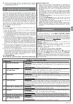
5.3 - Funkcje szczególne

5.3.1 - Funkcja: “Uruchom zawsze”

Ta funkcja umożliwia funkcjonowanie automatyki również w przypadku, kiedy 

jakieś urządzenie zabezpieczające nie funkcjonuje prawidłowo lub jest niezdat-

ne do użytku.

Jest wtedy możliwe sterowanie automatyką w trybie ręcznym (“

w


obecności 

użytkownika

”), postępując w następujący sposób:

01.

 Wyślij z pomocą nadajnika lub przełącznika kluczowego, itp. polecenie, 

aby uruchomić bramę. Jeżeli wszystkie urządzenia funkcjonują prawidło-

wo brama będzie działać prawidłowo, w przeciwnym przypadku należy 

postępować jak opisano niżej:

02.

 w ciągu 3 sekund ponownie uaktywnij polecenie i przytrzymaj sygnał (przy-

cisk, przekręcony kluczyk itp.);

03.

 po upływie około 2 sekund brama wykona żądany manewr w trybie ręcz-

nym (“

w


obecności użytkownika

”), czyli będzie się poruszać wyłącznie 

dopóki sygnał będzie aktywny.

Jeżeli urządzenia zabezpieczające nie funkcjonują prawidłowo, lampa ostrze-

gawcza wykona kilka krótkich błysków, umożliwiających rozpoznanie rodzaju 

problemu (przeczytaj rozdział 6 - Tabela 10).

5.3.2 - Funkcja: “Zawiadomienie o konserwacji”

Ta funkcja służy do sygnalizowania, kiedy należy wykonać przegląd automaty-

ki. Zawiadomienia o konserwacji następuje przy pomocy lampki podłączonej 

do wyjścia S.C.A., w przypadku, kiedy to wyjście jest zaprogramowane, jako 

“Kontrolka konserwacji”. Różne sygnały kontrolki są podane w 

Tabeli 9

 .

Aby zaprogramować ilość manewrów do przeglądu przejrzyj 

Tabelę 8

 .

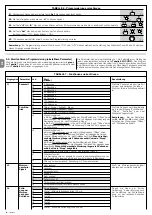
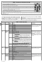
Tabela 9 - Sygnalizacja “Kontrolka konserwacji”

Ilość manewrów 

Sygnalizacja

Kontrolka świeci się przez 2 sekundy na początku każdego 

manewru .
Kontrolka miga przez cały czas trwania manewru.
Kontrolka miga stale.

Poniżej 80% limitu

Od 81% do 100% limitu
Powyżej 100% limitu

Uwaga

 – Kolorem szarym oznaczone są wartości ustawione fabrycznie.

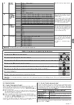
L8

L1
L2
L3
L4
L5
L6
L7
L8

Wynik 1-go manewru (ostatniego)
Wynik 2-go manewru
Wynik 3-go manewru
Wynik 4-go manewru
Wynik 5-go manewru
Wynik 6-go manewru
Wynik 7-go manewru
Wynik 8-go manewru

Umożliwia  sprawdzenie  typu  ano-

malii, która nastąpiła podczas wyko-

nywania ostatnich 8 manewrów .

Patrz TABELA 12 - Wykaz historii 

anomalii .

Wykaz  

anomalii

L7

L1
L2
L3
L4
L5
L6
L7
L8

500
1000
1500
2500
5000
10000
15000
20000

Ustala ilość manewrów, po przekroc-

zeniu której centrala zasygnalizuje 

ko nieczność  wykonania  przeglądu 

au tomatyki; przeczytaj paragraf 5 .3 .2 . 

– Zawiadomienie o konserwacji .

Zawiado-

mienie o 

konserwacji

L6

L1
L2
L3
L4
L5
L6
L7
L8

Furtka 1 (otwarcie skrzydła 2 na 1/4 pełnego otwarcia)
Furtka 2 (otwarcie skrzydła 2 na 1/2 pełnego otwarcia)
Furtka 3 (otwarcie skrzydła 2 na 3/4 pełnego otwarcia)
Furtka 4 (całkowite otwarcie skrzydła 2)
Częściowe 1 (otwarcie obu skrzydeł na 1/4 otwarcia “minimalnego”)
Częściowe 2 (otwarcie obu skrzydeł na 1/2 otwarcia “minimalnego”)
Częściowe 3 (otwarcie obu skrzydeł na 3/4 otwarcia “minimalnego”)
Częściowe 4 (pełne otwarcie obu skrzydeł równe otwarciu “minimalnemu”)

Reguluje rodzaj otwarcia połączonego 

z poleceniem “otwarcie częściowe 1”.

Na poziomach L5, L6, L7, L8; przez 

ot warcie “minimalne” przyjmowane 

jest mniejsze otwarcie spośród M1 i 

M2; na przykład, jeżeli M1 otwiera się 

na 90° a M2 na 110°; otwarcie mini-

malne wynosi 90°

Furtka dla 

pieszych 

lub 

częściowe 

otwarcie

L5

L1
L2
L3
L4
L5
L6
L7
L8

Poziom 1 - Siła minimalna
Poziom 2 -  . . .
Poziom 3 -  . . .
Poziom 4 -  . . .
Poziom 5 -  . . .
Poziom 6 -  . . .
Poziom 7 -  . . .
Poziom 8 - Siła maksymalna

Reguluje siłę obu silników.

Siła  

siłowników

PL

Summary of Contents for MC824H

Page 1: ...tions et avertissements pour l installation et l utilisation ES Instrucciones y advertencias para la instalaci n y el uso DE Installierungs und Gebrauchsanleitungen und Hinweise PL Instrukcje i ostrze...

Page 2: ...2 1 232 mm 310 mm 122 mm 2a d i g b f d h g b e a f c G 2b B A C C C C E F D...

Page 3: ...3 4 5 FLASH ELS S C A OPEN CLOSE BLUEBUS TX 24V 4W RX P P NC NO C C NO NC STOP P P STOP 24 Vcc 6 205 237 3 C A B...

Page 4: ...10 9 8 7...

Page 5: ...N 12453 EN 12635 and EN 13241 1 in particular which enable conformity of the automated functionality to be de clared In the light of the above all work involving installation connection testing and ma...

Page 6: ...vice must have a gap between contacts that ensures complete disconnection in the conditions of overvoltage category III in compliance with installation regula tions If necessary this device guarantees...

Page 7: ...1 L2 L3 L4 L5 L6 L7 L8 TABLE 4 Position Led Description 3 7 1 Learning in automatic mode 01 Press and hold down Set and keys at the same time 01 First connect the electric power cable fig 4 and secure...

Page 8: ...stop the manoeuvre To memorise the position press and hold down the Set key for at least 3 seconds and then release it after 2 seconds LED L1 remains on and on releasing the Set key LED L2 begins flas...

Page 9: ...door specifying at least the following data type of automation name and address of manufacturer responsible for commis sioning serial number year of construction and CE mark 4 Compile the Operation ma...

Page 10: ...mand persists for more than 2 seconds a Stop is performed Step by step 2 less than 2 sec generates partial opening Hold to run the manoeuvre is performed only if the transmitted command persists if th...

Page 11: ...ong as the control is activated If the safety devices do not operate the flashing light flashes a few times to indi cate the kind of problem see chapter 6 Table 10 5 3 2 Function Maintenance warning T...

Page 12: ...he motors encountered excessive resistan ce identify the cause and if necessary increase the level of force of the motors 4 short flashes 1 second pause 4 short flashes STOP input activation At the st...

Page 13: ...pening of two leafs to 1 2 of normal opening It causes an opening manoeuvre after which the automa tion is blocked the control unit accepts no further com mands with the exception of Step by step high...

Page 14: ...Vdc 21 Wmax lamp electric lock 12Vac 15 VAmax other outputs all types 1 lamp or relay 24Vdc 30 and 50 4 Wmax TECHNICAL CHARACTERISTICS OF THE PRODUCT PRODUCT MAINTENANCE 8 Regular maintenance is neede...

Page 15: ...lla Direttiva 2006 42 CE ex 98 37 CE Direttiva Mac chine e in particolare le norme EN 12445 EN 12453 EN 12635 e EN 13241 1 che consentono di dichiarare la conformit dell automazione In considerazione...

Page 16: ...anovra di apertura possibilit di collegare con tatti di tipo NA CLOSE ingresso per dispositivi di comando che intervenendo provo cano solo la manovra di Chiusura possibilit di collegare contatti di ti...

Page 17: ...tipo di lampeggio emesso in questa fase non significativo verificare che il lampeggiante collegato all uscita FLASH sia spento Se tutto questo non avviene necessario togliere l alimentazione elettric...

Page 18: ...ccanico d Chiusura veloce dei motoriduttori M1 e M2 Avvertenze Se la prima manovra a non chiude l anta comandata dal motore M1 ma quella comandata da M2 premere il tasto t oppure u per fermare la fase...

Page 19: ...collegamenti elettrici effettuati l analisi dei rischi presenti e le relative solu zioni adottate la dichiarazione di conformit del fabbricante di tutti i dispositivi utilizzati e la dichiarazione di...

Page 20: ...so e Apre provocano l inversione del movimento cio l apertura delle ante invece il comando Chiude non provoca nessun effetto Se il comando inviato permane per pi di 2 secondi viene eseguito uno Stop P...

Page 21: ...collegata all Uscita S C A quando questa uscita pro grammata come Spia manutenzione Le diverse segnalazioni della lampada spia sono riportate in Tabella 9 Per programmare il valore limite delle manov...

Page 22: ...ovre consecutive o di manovre per ora Attendere alcuni minuti in modo da far ritornare il limitatore di ma novre sotto il limite massimo 5 4 Cancellazione della memoria Per cancellare la memoria della...

Page 23: ...tallazione di manutenzione e di diagnosi dell intera automazio ne Per accedere al connettore necessario procedere come mo strato in fig 9 e collegare il connettore nell apposita sede L Oview pu essere...

Page 24: ...12Vdc 21 Wmax elettroserratura 12Vac 15 VAmax altre uscite tutti i tipi 1 lampada o rel 24Vdc 30 e 50 4 Wmax CARATTERISTICHE TECNICHE DEL PRODOTTO 10 Italiano MANUTENZIONE DEL PRODOTTO 8 Per mantenere...

Page 25: ...TENTION Conform ment la plus r cente l gislation europ en ne la r alisation d un vantail ou d un portail automatique doit res pecter les normes pr vues par la Directive 2006 42 CE ex 98 37 CE Directiv...

Page 26: ...e avec l encombrement total du produit voir fig 1 V rifier que la surface choisie pour l installation du produit est solide et peut garantir une fixation stable V rifier que la zone de fixation de l o...

Page 27: ...ir Tableau 4 Dans le mode mixte il est possible d effectuer la proc dure automatique puis avec la proc dure manuelle de modifier une ou plusieurs positions l excep tion des positions 0 et 1 fig B qui...

Page 28: ...3 s puis la rel cher au bout de 2 s la led L5 reste allum e et quand on rel che la touche Set la led L6 commence clignoter la led L6 clignote position SC de M1 Pour commander et porter le moteur 1 da...

Page 29: ...la norme EN 12445 et ventuellement si le contr le de la force de l o p rateur est utilis comme auxiliaire du syst me pour la r duction de la for ce d impact essayer et trouver le r glage qui donne les...

Page 30: ...x cut dans la man uvre de fermeture les commandes Pas pas et Ouverture provoquent l inversion du mouvement c est dire l ouverture des vantaux par contre la commande Fermeture ne provoque aucun effet S...

Page 31: ...quand cette sortie est programm e comme Voyant maintenance Les diff rentes signalisations du voyant sont indiqu es dans le Tableau 9 Pour programmer la valeur limite des man uvres de maintenance voir...

Page 32: ...ne commande et ventuellement teindre aussi l alimentation si l tat persiste il pourrait y avoir une panne grave et il faut remplacer la carte lectronique Attendre quelques minutes de mani re que le li...

Page 33: ...e galement d effectuer la mise jour du Micrologiciel Si un r cepteur radio appartenant la famille OXI est pr sent dans la logique de commande en utilisant l Oview il est pos sible d ac c der aux param...

Page 34: ...VAmax autres sorties tous les types 1 lampe ou relais 24 Vcc 30 et 50 4 Wmax CARACT RISTIQUES TECHNIQUES DU PRODUIT MAINTENANCE DU PRODUIT 8 Pour maintenir un niveau de s curit constant et pour garan...

Page 35: ...ropea la ejecuci n de un port n o puerta autom tica debe cumplir las normas previstas por la Directiva 2006 42 CE ex 98 37 CE Directiva de M quinas y en con creto las normas EN 12445 EN 12453 EN 12635...

Page 36: ...talaci n del producto sea s li da y que pueda garantizar una fijaci n estable Controle que la zona de fijaci n no pueda inundarse prevea el montaje del producto levantado del suelo Controle que el esp...

Page 37: ...la l nea el ctrica de alimentaci n es necesario montar un dispositivo que asegure la desconexi n completa del automatismo de la red El dispositivo de desconexi n deber tener una distancia de apertura...

Page 38: ...el pulsador para detener el movimiento Para memorizar la posi ci n pulse y mantenga pulsado el pulsador Set durante al menos 3 s y despu s su ltelo despu s de 2 s el led L5 quedar encendido y al solta...

Page 39: ...resultados 4 2 Puesta en servicio La puesta en servicio puede llevarse a cabo s lo despu s de haber ENSAYO Y PUESTA EN SERVICIO 4 Espa ol 5 TABLA 5 Funciones de primer nivel Led Funci n Descripci n L1...

Page 40: ...portamien to de los mandos Abrir y Cerrar Funci n Paso a Paso L3 L1 L2 L3 L4 L5 L6 L7 L8 Muy lenta Lenta Media R pida Muy r pida Rapid sima Abrir r pido Cerrar lento Abrir rapid simo Cerrar medio Regu...

Page 41: ...os operaciones de mantenimiento v ase la Tabla 8 5 4 Borrado de la memoria Para borrar la memoria de la central y restablecer todas las configuraciones de f brica proceda de la siguiente manera pulse...

Page 42: ...ellos cortos pausa de 1 segundo 3 destellos cortos Activaci n de la funci n Detecci n Obst culos de limitador de fuerza 4 destellos cortos pausa de 1 segundo 4 destellos cortos Activaci n de la entrad...

Page 43: ...y conecte el conector en su alojamiento El Oview puede conectarse a varias 5 Centrales simult neamente hasta 5 sin tomar ninguna precauci n hasta 60 respetando las advertencias respectivas y puede que...

Page 44: ...otras salidas todos los tipos 1 bombilla o rel 24Vdc 30 y 50 4 W m x CARACTER STICAS T CNICAS DEL PRODUCTO MANTENIMIENTO DEL PRODUCTO 8 Para mantener el nivel de seguridad constante y para garantizar...

Page 45: ...op ischen Gesetzgebung muss die Ausf hrung einer Automatikt r oder eines ebensolchen Tors den Normen der Richtlinie 2006 42 CE vorher 98 37 EG Maschinen richtlinie und im Besonderen den Normen EN 1244...

Page 46: ...eitet bis h chstens 40 m muss ein Kabel mit einem h heren Schnitt verwendet werden 2x1 mm2 Anmerkung 3 Diese beiden Kabel 2 k nnen mit nur einem Kabel 4 x 0 5 mm2 ersetzt werden Anmerkung 4 Diese beid...

Page 47: ...P P und STOP verbleibt auch wenn die Funktion Stand By in der Karte aktiviert wird 3 4 Adressierung der mit MC824H angeschlossenen Vorrich tungen Um der Steuerung zu erm glichen die am System Bluebus...

Page 48: ...e Taste oder dr cken und gedr ckt halten Nach Erreichen der Position die Taste freigeben um die Bewegung zu stoppen Um die Position zu speichern die Taste Set mindestens 3 Sek dr cken und gedr ckt hal...

Page 49: ...lung die besten Ergebnisse erzielt werden 4 2 Inbetriebsetzung Die Inbetriebsetzung darf erst erfolgen nachdem alle Abnahmephasen ABNAHME UND INBETRIEBSETZUNG 4 TABELLE 5 Funktionen erstes Niveau LED...

Page 50: ...erhalten der Steuerungen ffnen und Schlie en ge ndert Schrittbe trieb L3 L1 L2 L3 L4 L5 L6 L7 L8 Sehr langsam Langsam durchschnittlich Schnell Sehr schnell u erst schnell ffnet schnell schlie t langsa...

Page 51: ...pe wenn dieser Ausgang als Wartungsmeldeleuchte programmiert ist Die verschiedenen Anzeigen der Meldeleuchte sind in Tabelle 9 aufgef hrt Um den Grenzwert der Wartungsbewegungen zu programmieren siehe...

Page 52: ...wegung erfolgte eine Ausl sung der mit dem Eingang STOP verbundenen Vorrichtungen Ursache berpr fen 5 Mal kurzes Blinken 1 Sekunde Pause 5 Mal kurzes Blinken Fehler in den internen Parametern der Steu...

Page 53: ...anzen Automatisie rung erm glicht Um Zugang zu dem Stecker zu erhalten wie in Abb 9 vorge hen und den Stecker in den hierf r vorgesehenen Einsatz stecken Oview kann mit mehreren Steuerungen gleichzeit...

Page 54: ...enschaften des Ausgangs passen aufgrund der Programmierung an Blinkleuchte Lampe 12Vdc max 21 W Elektroschloss 12Vac max 15 VA Andere Ausg nge alle Arten 1 Lampe oder Relais 24 Vdc 30 und 50 max 4 W T...

Page 55: ...mi przewidzianymi przez Dyrektyw 2006 42 WE ex 98 37 WE Dyrektywa Maszynowa i w szczeg lno ci normami EN 12445 EN 12453 EN 12635 i EN 13241 1 kt re pozalaj na zade klarowanie zgodno ci automatu W zwi...

Page 56: ...Sprawd czy strefa mocowania urz dzenia nie jest nara ona na zalanie ewentualnie zamontuj urz dzenie na odpowiedniej wysoko ci nad ziemi Sprawd czy przestrze znajduj ca si wok urz dzenia umo liwia atw...

Page 57: ...arantuje ca kowi te od czenie automatyki od sieci Urz dzenie roz czaj ce zasilanie musi gwa rantowa odleg o pomi dzy stykami umo liwiaj c ca kowite roz czenie w warunkach zatwierdzonej III kategorii p...

Page 58: ...ku Set zaczyna miga dioda L6 dioda L6 miga po o enie SC M1 Aby ustawi si ownik 1 w po o eniu SC rys B wci nij i przytrzymaj przycisk lub Po uzyskaniu wymaganego po o enia zwolnij przycisk aby za trzym...

Page 59: ...as trwania przerwy pomi dzy wci ni ciem kolejnych przycisk w wynosi 10 sekund Po up ywie tego czasu procedura ko czy si automatycznie zostan zapami tane funkcje ustawione do tej chwili PROGRAMOWANIE 5...

Page 60: ...L7 i L8 ulega zmianie r wnie zachowanie polece Otwieranie i Zamykanie Funkcja Krok po Kroku L3 L1 L2 L3 L4 L5 L6 L7 L8 Bardzo niska Niska rednia Du a Bardzo du a Maksymalna Otwieranie szybkie L4 Zamyk...

Page 61: ...wiadomienia o konserwacji nast puje przy pomocy lampki pod czonej do wyj cia S C A w przypadku kiedy to wyj cie jest zaprogramowane jako Kontrolka konserwacji R ne sygna y kontrolki s podane w Tabeli...

Page 62: ...ch Sygna steruj cy nie zosta wy czony i blo kuje to wykonanie innych polece Automatyka zosta a zablokowana pr zez po lecenie Zablokuj automatyk Zadzia anie funkcji Wykrywanie przeszk d poprzez sygna z...

Page 63: ...gramator Oview panel zasilany ener gi s oneczn Solemyo i akumulator awaryjny mod PS324 7 1 Pod czenie odbiornika radiowego Centrala steruj ca zawiera z cze umo liwiaj ce pod czenie odbiornik w radiowy...

Page 64: ...amowania lampa ostrzegawcza ar wka 12Vps 21 Wmax zamek elektryczny 12Vpp 15 VAmax inne wyj cia wszystkie rodzaje 1 ar wka lub przeka nik 24Vps 30 i 50 4 Wmax PARAMETRY TECHNICZNE URZ DZENIA KONSERWACJ...

Page 65: ...het afgedankte product LET OP Volgens de meest recente Europese wetgeving moet een automatische deur of hek de voorschriften van de richtlijn 2006 42 EG ex 98 37 EG Machinerichtlijn in acht nemen en...

Page 66: ...de totaalafmetingen van het product zie afb 1 Controleer of het voor de installatie van het product gekozen vlak van stevig materiaal is en een stabiele bevestiging kan verzekeren Controleer of er op...

Page 67: ...worden uitgevoerd Op de elektrische voedingsleiding dient een inrichting te worden aangebracht dat volledige afkoppeling van de automatisering van het elektriciteitsnet verze kert Deze afkoppelinricht...

Page 68: ...ndrukken en vasthouden Nadat de positie bereikt is de toets loslaten om de manoeuvre te stoppen Om de positie in het geheugen op te slaan de toets Set minstens 3 sec ingedrukt houden en vervolgens wee...

Page 69: ...or het systeem voor de reductie van de stootkracht uit te proberen welke afstelling de beste resultaten geeft 4 2 Inbedrijfstelling Inbedrijfstelling kan alleen plaatsvinden nadat alle fasen van de ei...

Page 70: ...rdt ook het gedrag van de instructies Open en Sluit gewijzigd Functie Stap voor stap L3 L1 L2 L3 L4 L5 L6 L7 L8 Heel langzaam Langzaam Gemiddeld Snel Zeer snel Hoogste snelheid Open snel Sluit langzaa...

Page 71: ...de ingangsled is van de te wijzigen parameter 04 Houd de toets Set ingedrukt tot punt 06 is afgewerkt 05 Wacht circa 3 seconden totdat de led gaat branden die het actuele niveau van de te wijzigen pa...

Page 72: ...ng Fout Bluebus systeem De controle van de inrichtingen die zijn aangesloten op het Bluebus syste em die aan het begin van de manoeuvre wordt uitgevoerd stemt niet ove reen met de inrichtingen die ged...

Page 73: ...matisering met de besturingseenheid verbonden blijven In dit geval kan hij gebruikt worden om de instructies rechtstreeks naar de besturingseenheid te sturen met behulp van het specifieke menu gebrui...

Page 74: ...Vdc 30 en 50 4 Wmax TECHNISCHE GEGEVENS VAN HET PRODUCT 10 Nederlands NL ONDERHOUD VAN HET PRODUCT 8 Om de veiligheid op een constant niveau te houden en een zo lang mogelijke levensduur van de gehele...

Page 75: ...ti applicabili alle seguenti norme EN 13241 1 2003 EN 12445 2002 EN 12453 2002 EN 12978 2003 A1 2009 Oderzo 29 giugno 2013 Ing Luigi Paro Amministratore Delegato IT EN CE declaration of conformity and...

Page 76: ...ormas EN 13241 1 2003 EN 12445 2002 EN 12453 2002 EN 12978 2003 A1 2009 Oderzo 29 de Junio 2013 Ing Luigi Paro Administrador Delegado D claration CE de conformit et d claration d incorporation de quas...

Page 77: ...erzo dnia 29 Czerwiec 2013 roku In Luigi Paro Cz onek Zarz du Sp ki CE Konformit tserkl rung und Integrierungserkl rung einer Fastmaschine Erkl rung in bereinstimmung mit den folgenden Richtlinien 200...

Page 78: ...volgende geharmoniseerde normen EN 61000 6 2 2005 EN 61000 6 3 2007 Daarnaast voldoet het product aan de volgende richtlijn volgens de vereisten die voorzien zijn voor niet voltooide machines samenst...

Page 79: ...the control unit programming and adjustment parameters this is the responsibility of the installer Power supply failure or absence while waiting for the installer or the electrical power supply to re...

Page 80: ...ntervento del vostro installatore di fiducia Non modificare l impianto e i parametri di programmazione e di regolazione della centrale di comando la responsabilit del vostro installatore Rottura o ass...

Page 81: ...er de le r parer mais contacter l installateur de confiance Ne pas modifier l installation ni les param tres de program mation et de r glage de la logique de commande la responsa bilit en incombe l in...

Page 82: ...ique la instalaci n ni los par metros de programa ci n y de regulaci n de la central de mando la responsabilidad es del instalador Rotura o falta de alimentaci n mientras espera que llegue el ins tala...

Page 83: ...ie selbst Reparaturen auszuf hren sondern fordern Sie den Eingriff Ihres Vertrauensinstallateurs an Die Anlage und die Programmierungs und Einstellungspara meter der Steuerung nicht ndern diese Verant...

Page 84: ...stalatora Nie modyfikuj instalacji lub parametr w programowania i regulacji centrali steruj cej odpowiedzialno za jego bez pieczn regulacj ponosi instalator Uszkodzenie lub brak zasilania w oczekiwani...

Page 85: ...installatie en de programmeer en instellingspara meters van de besturingseenheid niet veranderen de verant woording hiervoor berust bij de installateur Defect of uitval van de stroomtoevoer in afwach...

Page 86: ......

Page 87: ......

Page 88: ...IST269R03 8_26 07 2013 www niceforyou com Nice SpA Oderzo TV Italia info niceforyou com...

Reviews: