4
STRAC2 Hardware Manual
920-0118 Rev B
03/26/21
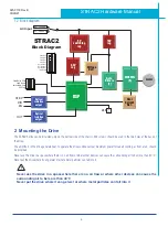
1.2 Block diagram
STEP
DIR
OUT
EN
Gate
Drivers
(3)
Optical
Isolation
output
Optical
Isolation
output
Over
Current
Det.
DSP
5V
switching
reg
MOSFETs
(6)
motor
Voltage
Det.
10V
reg
3.3V
reg
LED
STRAC2
Block Diagram
Step Noise Filter
Load Inertia
Smoothing Filter
Self Test
Step Res 1
Step Res 2
Step Res 3
Step Res 4
Current Set 1
Current Set 2
Current Set 3
Idle Current
90
~
135VAC
AC Input
135
~
240VAC
2 Mounting the Drive
The STRAC2 drive can be mounted only on the narrow side of the chassis. M4 screws should be used in the two holes at the back of
the drive.
The amplifiers in the drive generate heat. To operate the drive continuously at maximum power forced air cooling, as from a fan, should
be provided.
Never use the drive in a space where there is no air flow or where other devices can cause the surrounding air to be more than 40 °C.
Never put the drive where it can get wet or where metal particles can fall into it.
Never use the drive in a space where there is no air flow or where other devices can cause the
surrounding air to be more than 40 °C
Never put the drive where it can get wet or where metal particles can fall into it


