Settings
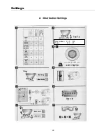
A: Distribution Settings
Carrying out the calibration test
1) Fixed unit test
1
Set the distribution as indicated in the manual (plugs, baffle, plate, shutters etc.).
2
Put the grain in the seed box
on the day of sowing
(5 kg of rape, 150 kg of cereal) and carry
out the following test.
3
Set
the variator to the mark indicated in the table (see flow rate table and calibration).
4 Start
distribution: a
minimum
of
25 turns
of the crank (the trough may be filled), or
100 turns
for rape.
5 Carry
out
the test by completing the appropriate number of turns for the width of the seed drill.
N B
Turn steadily at
1 turn per second.
6
Weigh
the quantity collected in the trough using accurate scales.
7
Multiply by 40
to obtain the quantity per hectare or use the calculator (see next page).
8 Correct
the variator setting (lower the lever completely then bring it back up to the required
value).
9 Reset
the area meter to zero after the calibration test.
10
The most representative test is one carried out under real working conditions.
After sowing a hectare, carry out a further check (proceed as above from step
5
).
Drill Width (Metres)
Number of turns with
the crank
240G 62.5
300G 50
Checking the distribution system
Distribution of seed to the seed tubes should be checked at regular intervals through out the day, for
example every hour.
•
Check both sides of the drill appear to be delivering the same amount of seed to each coulter.
•
Manually turn the drive wheel to ensure seed is flowing out of each coulter.
•
Engage tramline mechanism and repeat the above procedure, Note the voltage the tramline system
receives from the tractor affects the way in which the tramline will work
. IF THE TRACTOR IS
SUPPLING AN INVERSE POLARITY VOLTAGE TO THE TRAMLINER, THE TRAMLINE
MECHANISM WILL WORK IN THE OPPOSITE MANNER ,i.e TRAMLINE WHEN IT SHOULD’NT
AND NOT TRAMLINE WHEN IT SHOULD
•
When calibrating the seed box check each side of the drill is delivering the right amount of seed.
23
Summary of Contents for 240G
Page 9: ...Safety Instruction Decals Safety Stickers 9 ...
Page 10: ...Safety Instruction Decals 10 ...
Page 11: ...Safety Instruction Decals 11 25 ...
Page 12: ......
Page 22: ...Settings A Distribution Settings Size metres 2 40 3 00 Turns 62 5 50 22 ...
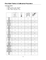
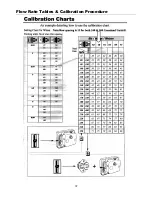
Page 37: ...Flow Rate Tables Calibration Procedure 37 ...
Page 38: ...Flow Rate Tables Calibration Procedure 38 ...
Page 39: ...Flow Rate Tables Calibration Procedure 39 ...
Page 40: ...Flow Rate Tables Calibration Procedure 40 ...
Page 43: ...Grassland Parts booklet 2007 grassland seeding line ...
Page 45: ...Grassland Main Chassis ...


