Start Up
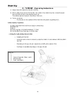
G : Turbine – Operating Instructions
1) Mechanical
•
Use the 1000 RPM power take-off
•
Maintain tractor engine rate during work
•
Do not engage the PTO on full load
2) Hydraulic
a) Specification
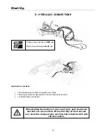
Warning and reminder: a number of checks need to be made on the tractor when using the hydraulic turbine
drive system. Consult your dealer.
1) The minimum oil flow rate required at working RPM is 30 liters/min
2) The oil pressure rises to 180 bars on start-up
3)
Feedback must imperatively be below 15 bar; otherwise extensive damage will be caused to
the hydraulic motor. If possible always try to run the oil back into the tractor, without any
restriction, i.e. put the return pipe for the hydraulic fan motor directly into the back of the
tractor without going through the spool valve.
4) When using a tractor with open center hydraulics, use the oil flow regulator on the tractor to control
the speed of the fan and
free flow the oil back to tank
. If there is no flow regulator on the tractor,
an inline flow regulator will be required for the motor, again free flow back to tank.
5) When using a tractor with closed center hydraulics (John Deere) use a Series 3 SCV valve (motor
Spool). If this is not fitted refer to your John Deere Dealer
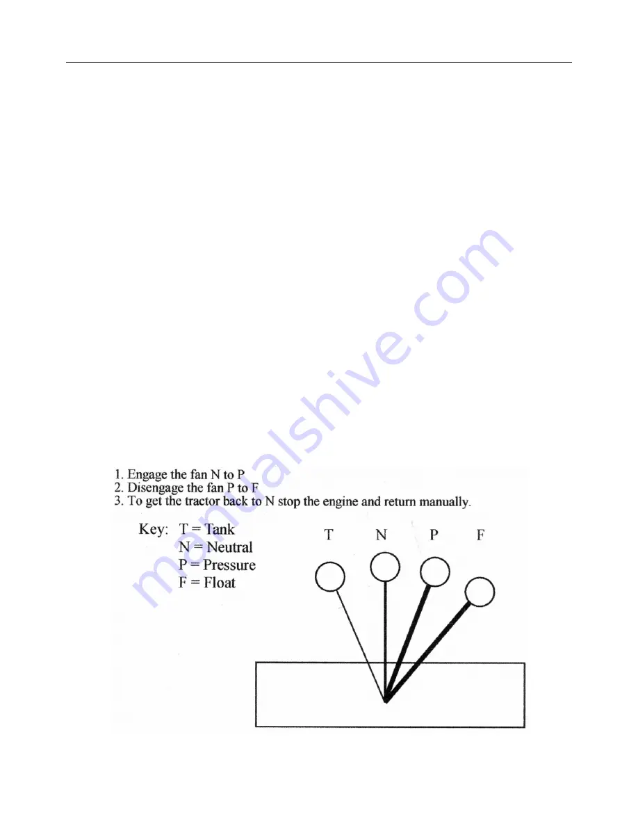
6) When using the spool lever to control the hydraulic fan consider the points listed below.
Failure to disengage the fan through the float facility on the spool lever, will ‘dead head’ the hydraulic motor,
this may then destroy the manometer or damage the fan motor seals.
18
Summary of Contents for Tandem Uni-Drill DP400A
Page 9: ...Safety Regulations Safety Stickers 9 ...
Page 17: ...Start Up G TURBINE 17 ...
Page 23: ...Settings A Distribution Settings 23 ...
Page 32: ...Settings H Tramline Track Width 32 ...
Page 41: ...Flow Rate Tables Calibration Procedure 41 ...
Page 42: ...Flow Rate Tables Calibration Procedure 42 ...
Page 43: ...Flow Rate Tables Calibration Procedure 43 ...
Page 44: ...Flow Rate Tables Calibration Procedure 44 ...
Page 45: ...Flow Rate Tables Calibration Procedure 45 ...
Page 48: ...DP400A and DP600A Parts booklet 2002 seeding line ...
Page 52: ...2002 DP600A markers ...
Page 54: ...Marker Circuit Diagram ...
Page 55: ...W Seed box hopper extension ...
Page 56: ...W Seed box Peg Wheels ...
Page 57: ...W Seed box Distributor Assembly ...
Page 58: ...W Seed box Distributor Assembly ...
Page 59: ...W Seed box Variator Assembly W Seed box Variator Assembly ...
Page 60: ...W Seed box half width shut off ...
Page 61: ...W Seed box Venturi System ...
Page 62: ...W Seed box Drive Wheel Assy ...
Page 63: ...W Seed box Wind turbine Assy ...
Page 64: ...W Seed box Air Intake ...
Page 65: ...W Seed box RDS system ...


