3
Assembly Diagram
Illustration # 2
3.)
2.)
Illustration # 1
R
EAD
T
HROUGH
I
NSTRUCTIONS
FROM
BEGINNING
TO
END
BEFORE
STARTING
TO
ASSEMBLE
UNIT
.
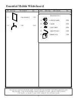
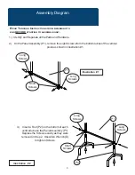
Identify and Separate all the Parts and Hardware.
On the Panel Assembly (P1), remove the eight Screws from the bottom tubes of the vertical
posts as shown in illustration #1.
1.)
P1
Long
Screws
Short
Screws
Long
Screws
Insert a Foot (P2) on the bottom of each
vertical tube on the Panel Assembly (P1).
Replace the Screws exactly as they were
removed in Step 2. Use Allen Wrench (D)
to tighten Screws.
P1
P2
Short
Screws
Long
Screws
Long
Screws


