Page 4
Page 9
First assembly
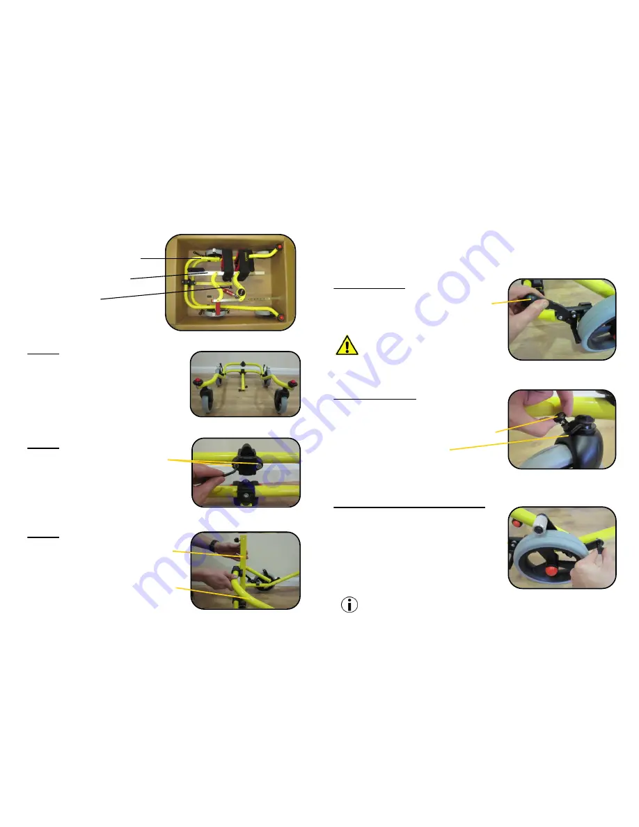
Contents of the box:
1) Base frame Assembly
2) Support Framework
3) Locking Pin
(4mm and 5mm Allen key provided
in the plastic bag with this manual)
Step 1
Unpack the Base frame assembly and
place on a flat surface as shown.
Step 2
Loosen both of the socket screws using
the 5mm Allen key provided and remove
the front half of the clamp.
Step 3
Lift the square post so it is in a vertical
position.
At the same time lift the U-shaped metal
frame to meet the post so that it is sitting
inside the clamp as shown.
Additional features
These features can be activated for use by following the procedures
outlined below or disengaged when not needed:
Parking Brake
To activate the parking brake, pull down on the
black plastic lever until it engages with the tyre
and locks into position. To disengage the brake,
push up on the plastic lever.
The parking brake should always
be engaged when first putting the
user into the walker.
Directional Lock
The directional lock is used to lock the castor
wheels so they can only travel straight.
To activate the lock, turn the plastic spring pin
through 90° and let the metal pin fall into the
hole on the plastic castor fork.
To disengage the lock, pull the plastic spring pin
up and twist it through 90° to lock out of position.
Anti Roll-Back Lock (optional)
The anti roll-back lock is used to stop the walker
moving backwards when the user is trying to walk.
To engage the Lock, pull the plastic spring pin
out and let the knurled metal bearing rest on
the tyre.
To disengage the lock, pull the plastic spring pin
out and guide it back into the receiving hole.
The anti roll-back lock is an optional
extra and may not be supplied with your device.


