background image

 
       Manual Part No: 931760-01                                     MV1 Gas Fryer 


 - 22 – 

       Manual Rev No: 1 


Service and Maintenance (cont.) 

 
Fault Finding 


Fault Possible 

Cause 

Remedy 

High Limit Thermostat has tripped 

Reset high limit thermostat.  Check 
calibration of operating thermostat, as this 
may be too high causing the high limit to 
trip.  Operating thermostat should cut off 
the main burners at 180ºC when set to 
maximum temperature.  If operating 
thermostat calibration is satisfactory, check 
high limit thermostat calibration as this may 
be set too low causing it to trip or become 
sensitive to vibration.  High limit thermostat 
should cut at approximately 216-218ºC.  
The oil temperature must not overshoot 
above 230ºC. 

Faulty High Limit Thermostat (open circuit) 

Replace 

Faulty thermocouple (low milli-voltage). 

Replace. 

Faulty wiring or connections between 
Thermocouple and High Limit Thermostat. 
(no continuity) 

Check wires and connections. 
Repair/replace as required. 

Pilot will not establish. 

Thermocouple tip not correctly aligned with 
pilot flame or pilot flame too small. (low 
milli-voltage) 

Clean or re-adjust as required 

Pilot misalign with main burners (poor cross 
lighting) 

Check and adjust as required to ensure 
satisfactory cross lighting. 

Pilot flame too small (poor cross lighting) 

Check clean/ re-adjust to ensure 
satisfactory cross lighting. 

Explosive Ignition when 
main burners light 

Gas pressure too low 

Investigate cause and correct. 

Is gas valve turned to on position?  

Rotate knob to on position. 

Thermopile failure 

Check milli-voltage 
Open circuit 300MV plus 
Closed circuit 100MV plus 

Pilot flame too small or not burning 
correctly(low milli-voltage from T/pile 

Check/adjust or replace pilot assembly as 
required. 

Thermostat failure contacts open or 
thermostat worn or damaged 

Replace Thermostat 

Pilot establishes but 
main burners will not 
light. 

Wiring fault or loose connection in 
thermostat or thermopile circuits. 

Check/ repair or replace as required.  

If main burners can not be turned on and off 
with the thermostat control knob.  Then 
suspect a failed capillary tube. 

Replace Thermostat 

Main Burners remain on 

If main burners can not be turned on and off 
with control thermostat knob.  Suspect an 
open circuit connection. 

Repair 


Summary of Contents for MV 1 SERIES

Page 1: ...MV 1 SERIES GAS FRYER OWNER S MANUAL Click here for Parts List Country of Destination GB and IE Manual Part No 931760 01 MV1 Gas Fryer 1 Manual Rev No 1 ...

Page 2: ...er 450 Fryer with Stainless Tank 450 Fryer with Stainless Tank 600 Fryer 600 Fryer 600 Fryer with Stainless Tank 600 Fryer with Stainless Tank 600 Fryer Twin Tank 600 Fryer Twin Tank 600 Fryer Twin Tank with Stainless Tank 600 Fryer Twin Tank with Stainless Tank 1 1 1 1 1 1 1 1 1 1 1 1 21 02 05 21 02 05 21 02 05 21 02 05 21 02 05 21 02 05 21 02 05 21 02 05 25 02 05 25 02 05 25 02 05 25 02 05 BSP h...

Page 3: ...tion 6 9 Gas Pressure Connection 6 Overall Dimensions 7 9 Installation 10 12 Important Note 11 Positioning 11 Checking Commissioning 12 User s Instruction 13 18 Important Note 13 Operation 14 16 Cooking Guide 16 Cleaning 17 18 Service Maintenance 19 25 Routine Maintenance 19 20 Fault Finding 21 Wiring Diagram 22 Instructions 23 25 Spare Parts 26 27 Warranty Cover Sheet 28 ...

Page 4: ...E REGULATIONS 2000 the requirements of the FIRE PRECAUTIONS ACT 1971 the HEALTH SAFETY AT WORK ETC ACT 1974 the BUILDING STANDARDS SCOTLAND CONSOLIDATION REGULATIONS 1971 Detailed recommendations are contained in British Standards BS5440 Part 1 2000 BS5440 Part 2 2000 BS5588 Part 0 1996 BS5588 Part 11 1997 BS6173 2001 An easily accessible stopcock must be fitted in the gas supply adjacent to the a...

Page 5: ...burns therefore the appliance should be positioned to minimise the possibility of accidental touching It is the supervisors responsibility to warn users to wear suitable protection and to follow correct operation and cleaning procedures For the details of your nearest Service Agent for all warranty and repair work you should contact The Service Manager Viscount Catering Limited Provincial Park Net...

Page 6: ...atural Gas Propane Gas 450 Fryer 3 03mm 1 84mm 600 Fryer 3 42mm 2 10mm 600 Twin Tank Fryer 2 36mm 1 50mm Dimensions 600 Twin Tank Fryer 450 Fryer 600 Fryer Width 600mm 23 6 450mm 17 7 600mm 23 6 Depth 750mm 29 5 750mm 29 5 750mm 29 5 Height 930mm 36 6 930mm 36 6 930mm 36 6 Pan Area W x D 2 x 230mm x 480mm 310mm x 480mm 460mm x 480mm 2 x 9 x 18 8 12 2 x 18 8 18 1 x 18 8 Oil Capacity 2 x 17 Litres 2...

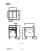
Page 7: ...Specification cont 150 1040 900 176 62 450 700 751 751 312 483 450 Fryer Manual Part No 931760 01 MV1 Gas Fryer 7 Manual Rev No 1 ...

Page 8: ...Specification cont 150 1040 900 176 62 600 700 751 751 462 483 600 Fryer Manual Part No 931760 01 MV1 Gas Fryer 8 Manual Rev No 1 ...

Page 9: ...Specification cont 150 1040 900 176 62 600 700 751 751 234 483 600 Twin Tank Fryer Manual Part No 931760 01 MV1 Gas Fryer 9 Manual Rev No 1 ...

Page 10: ...orting the weight of the appliance TO COMPENSATE FOR SOME UNEVENNESS OF THE FLOOR THE APPLIANCE FEET ARE ADJUSTABLE THE FLOOR MUST BE FIRE PROOF If it is not or if any adjacent wall or surface is made of a combustible material then the installer MUST ensure that the requirements of the LOCAL FIRE REGULATIONS are observed Positioning In order for us to meet the requirements of British Standard BS E...

Page 11: ...wise to raise the corner Gas Connection Natural Gas The size of the supply pipe should be no smaller than BSP and an easily accessible stopcock must be fitted in the gas line adjacent to the appliance An armoured flexible pipe of a GAS COUNCIL APPROVED PATTERN is recommended NOTE Due to the pressure loss through the snap connection fitting on flex hoses you must fit a flexible hose to all 600mm wi...

Page 12: ...D AS FOLLOWS On the gas governor part of Control Valve Remove the cap in order to gain access to the pressure adjusting screw Turn the pressure adjusting screw clockwise to increase the pressure or anti clockwise to decrease it When the pressure reading is correct refit the cap to the governor Turn the gas supply to the unit OFF at the stopcock and disconnect the manometer U tube Ensure that the p...

Page 13: ...e necessary you are advised to contact your nearest CORGI Confederation for the Registration of Gas Installers Service Engineer immediately The need for regular servicing is detailed in the GAS SAFETY INSTALLATION USE REGULATIONS 2000 IF YOU THINK THAT GAS IS ESCAPING ACT IMMEDIATELY SHUT OFF THE GAS SUPPLY AT THE METER OR EMERGENCY CONTROL CONTACT THE SUPPLIER OF YOUR GAS IMMEDIATELY MAKE SURE TH...

Page 14: ...guished on releasing knob repeat steps 4 5 7 Turn the control knob anti clockwise to the ON position 8 Turn the thermostat knob to the required setting to light the main burners checking that they light before closing the door If the pilot goes out for any reason turn the control valve knob to the OFF position n and wait 3 minutes before re lighting This will allow the valves integral safety devic...

Page 15: ...rn OFF again Leave it for 30 seconds before repeating the 5 10 seconds cycle Continue to repeat until the fat has melted so that any remaining un melted pieces are free floating and then turn the thermostat to the required temperature Cooking Instructions With the thermostat knob turned to the required cooking temperature allow the oil or fat to heat up for about 20 minutes before starting to cook...

Page 16: ...ken Pieces 5 8 minutes 175 C Chipped Potatoes Blanched 3 minutes 165 C Chipped Potatoes Browning 1 2 minutes 190 C Chipped Potatoes Raw 4 5 minutes 190 C Doughnuts 3 4 minutes 170 C Fish Fillets 5 7 minutes 175 C Fritters 3 4 minutes 175 C Potato Crisps 2 minutes 190 C Scampi 3 4 minutes 175 C To Obtain Best Results Keep the pan clean Use good quality oil or fat which has high breakdown temperatur...

Page 17: ...e drain tap remove the safety chain and open the tap NOTE The oil or fat will flow more freely if it is still warm but on no account should the fat be filtered at frying temperatures 3 Remove the frying basket and also the strainer from the bottom of the pan and clean these thoroughly at the sink 4 Clean the inside of the pan with a clean cloth taking care not to damage the two thermostat phials i...

Page 18: ...esults from your cooking DO NOT POKE WIRE INTO BURNER PORTS OR ORIFICES TO CLEAR THEM OF OBSTRUCTION SEND FOR A QUALIFIED ENGINEER All gas taps and control knobs must operate smoothly and freely without sticking or jerking Re lubrication MUST be carried out by a QUALIFIED ENGINEER WE RECOMMEND THAT ALL EQUIPMENT IS SERVICED AT LEAST ONCE A YEAR BUT MAY BE AS FREQUENT AS 6 MONTHS OR LESS IF THE GAS...

Page 19: ...at both burners extinguish completely within 3 4 seconds 5 Turn the thermostat on again to 150 C and ensure that both burners cross light smoothly from the pilot 6 Check that the burner flames are uniform and there is no spillage of the flames away from the heat exchanger 7 Turn the thermostat OFF and blow out the pilot Check that the flame safety valve closes within 60 seconds this can be done by...

Page 20: ...Manual Part No 931760 01 MV1 Gas Fryer 20 Manual Rev No 1 ...

Page 21: ...ross the valve contacts TP TH TH the burner will re light allow to heat up carefully checking the oil temperature with a thermometer NOTE That the over heat thermostat operates between 225 C 230 C inclusive of over shoot and that the gas to the main burners goes out immediately 14 Remove the link wire from the operating thermostat 15 Allow to cool and press the reset button on the overheat thermos...

Page 22: ...ame or pilot flame too small low milli voltage Clean or re adjust as required Pilot misalign with main burners poor cross lighting Check and adjust as required to ensure satisfactory cross lighting Pilot flame too small poor cross lighting Check clean re adjust to ensure satisfactory cross lighting Explosive Ignition when main burners light Gas pressure too low Investigate cause and correct Is gas...

Page 23: ...Service and Maintenance cont Wiring Diagram TP TH TP TH THERMOSTAT GAS VALVE WHITE RED THERMOPILE THERMOCOUPLE PILOT HI LIMIT THERMOSTAT Manual Part No 931760 01 MV1 Gas Fryer 23 Manual Rev No 1 ...

Page 24: ...from the tank and withdraw the phial bulb Lift off the control valve cover and remove the two screws securing the override thermostat to its bracket and withdraw Disconnect the two wires noting their positions Replace the thermostat by reversing the above procedure ENSURE THAT THE THERMOSTAT PHIAL IS NOT KINKED HAS NO SHARP BENDS AND IS CORRECTLY LOCATED IN ITS HOLDER 3 Removing the Burner Pilot A...

Page 25: ...ng the Manifold to the tank The injectors can now be unscrewed from the manifold assembly To clean the injector brush off with a stiff bristle brush any dirt blow through the orifice to remove any blockage or restriction DO NOT POKE WIRE THROUGH THE INJECTOR ORIFICE Replace by reversing the above procedure 6 Removing a Thermocouple Open compartment door and lift off the control valve cover Remove ...

Page 26: ...as described above but substitute with parts listed below 450 Fryer Pilot injector 931767 12 x1 Burner Injector 931767 18 x2 600 Fryer Pilot injector 931767 12 x1 Burner Injector 931767 20 x2 600 Twin Tank Fryer Pilot Injector 931767 12 x2 Burner Injector 931767 16 x4 Finally fit replacement Data Plate and re test the appliance ...

Page 27: ...hermopile c w 600mm Lead 1 931767 04 Thermocouple c w Interrupter 1 931646 01 Door Handle 1 929947 01 Override Thermostat Jumo TCH Single Pole 1 921335 02 Door Catch 1 920522 G1 Drain Extension Tube 1 924116 G1 Fryer Basket 600 600 Twin Tank 1 or 2 924116 G3 Fryer Basket 450 mm 2 920429 G1 Strainer Guard Assembly 1 927590 G1 Tank Cover Assembly Aluminium 600 1 927590 G2 Tank Cover Assembly Alumini...

Page 28: ... NG to LPG 60F Spares Kit 931815 S4 Conversion Kit LPG to NG 60F Spares Kit 931815 S5 Conversion Kit NG to LPG 60F Twin Tank Spares Kit 931815 S6 Conversion Kit LPG to NG 60F Twin Tank Spares Kit XCMV1FSG LH LH Splashguard Assembly Optional XCMV1FSG RH RH Splashguard Assembly Optional Spare parts are available from Viscount Catering Ltd Provincial Park Nether Lane Ecclesfield Sheffield S35 9ZX Tel...

Page 29: ...The Company will not be obliged to repair or replace any goods if after examination the defect damage is found to be through accident misuse neglect incorrect installation or maintenance by other than approved engineers or any other cause beyond the reasonable control of the manufacturer EXCLUSIONS TO WARRANTY Normal routine maintenance is not covered and the warranty specifically excludes any pro...

Reviews: