background image

10

E

SP

AÑOL

CONTROLE  QUE  EL  PACIENTE  ESTÉ  CORRECTAMENTE  SENTADO  DURANTE  TODO  EL 
MOVIMIENTO DE ELEVACIÓN.

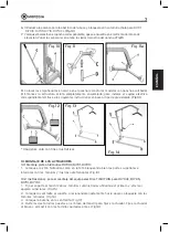
7.   Levante  el  paciente  hasta  la  altura  necesaria  manteniéndolo  en  posición  frontal  con 

respecto a quien lo asiste.

8.  Desbloquee las ruedas posteriores y traslade el paciente.
9.  Antes de comenzar el descenso del paciente, vuelva a bloquear las ruedas posteriores.
10.  Pulse  la  tecla  “descenso”  para  bajar  el  paciente  (en  el  modelo  RI710  la  pantalla  en  la 

centralita visualiza el brazo en movimiento).

 CONTROLE  QUE  EL  PACIENTE  ESTÉ  CORRECTAMENTE  SENTADO  DURANTE  TODO  EL 
MOVIMIENTO DE ELEVACIÓN.

DURANTE EL DESCENSO, AYUDE AL PACIENTE PARA QUE MANTENGA LA POSICIÓN
CORRECTA.

¡ATENCIÓN!
Durante  el  descenso  evite  que  el  paciente  encuentre  un  obstáculo  en  el  movimiento 
hacia abajo. En ese caso subir de nuevo el paciente y quitar el obstáculo.

PARADA DE EMERGENCIA
En  la  unidad  de  control  hay  un  pulsador  rojo  “STOP”,  cuyo  accionamiento  desactiva 
inmediatamente todos los mandos. Para rearmarlo, gire el pulsador rojo hasta que se dispare 
hacia afuera.

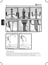
DESCENSO MECANICO DEL ACTUADOR
En caso de averías o de falta de electricidad hay un descenso de emergencia. Asegúrese de que el 
descenso manual/mecánico de emergencia se haga en condiciones de seguridad por el paciente. 
Para bajar mecanicamente el actuador presione la tuerca en plástico rojo hacia abajo y gírela en 
sentido antihorario. Para subir el actuador presione la misma tuerca y gírela en sentido horario. 
Una vez bajado el paciente ponel la tuerca roja en la posición inicial.

MANDOS DE EMERGENCIA
RI710: En la centralita hay dos teclas (flecha arriba y flecha abajo) que se pueden utilizar en lugar
de  las  mismas  teclas  del  mando  a  distancia  en  el  caso  de  que  ese  mismo  tenga  problemas  de 
funcionamiento.

INDICACIÓN DEL ESTADO DE CARGA DE LA BATERIA
En el mando hay un indicador de LED, que señala el estado de carga de la batería. El encendido
de todos los LEDs indica la carga completa de la batería, mientras que el encendido de un solo
LED avisa que la batería está descargada y requiere una recarga. 

RECARGA DE LAS BATERÍAS

¡ATENCIÓN!
Asegurese  de  que  el  botón  rojo  de  emergencia  “STOP”  esté  DESACTIVADO.  Para 
desactivarlo girar y tirar el botón rojo hacia si mismo.

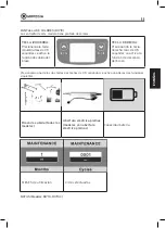
• Conecte el adaptador a la toma de la red de suministro y luego a la toma de la unidad de 
control después de quitar la tapa de protección
• En el cargador hay un led que está de color naranja durante de la recarga. Cargue la batería
hasta que ese led se vuelva de color verde
• Antes de utilizar la grua, recuerde desconectar siempre el adaptador para recargar las baterías
• Comience a cargar las baterías por lo menos 6 horas antes de utilizar la grua

Summary of Contents for RI700C

Page 1: ...MA RI700C_RI701_RI701C_RI703C_RI705_RI710_RI710C 02 A_ITA_07 2020 SOLLEVATORI ARKIMED MANUALE DI ISTRUZIONI ITALIANO...

Page 2: ...gio kit elettrico TiMOTION per RI703C RI705 RI710 RI710C pag 7 11 PRIMA DI OGNI USO PAG 8 12 ISTRUZIONI D USO PAG 9 12 1 Istruzioni d uso modelli idraulici RI700C RI701 RI701C pag 9 12 2 Istruzioni d...

Page 3: ...presente manuale Moretti S p A declina qualsiasi responsabilit su danni derivanti da un uso improprio del dispositivo o da un uso diverso da quanto indicato nel presente manuale Il produttore si riser...

Page 4: ...dispositivo al fabbricante e all autorit competente dello Stato membro in cui l utilizzatore e o il paziente stabilito 6 SIMBOLOGIA UTILIZZATA Codice prodotto Identificativo univoco del dispositivo M...

Page 5: ...C RI705 RI710 RI710C Pz 1 H Maniglia Pz 1 I Kit di assemblaggio Pz 1 J Impugnatura per cradle Pz 2 8 2 Attuatore idraulico RI700C 135 KG ri701 RI701C 180 KG Fig 2 8 3 KIT elettrico TiMOTION RI703C 135...

Page 6: ...tralina 9 ISTRUZIONI DI MONTAGGIO PER LA STRUTTURA DI TUTTI I MODELLI 1 Svitare la vite nella base della colonna Fig 5 2 Inserire la colonna nella cavit prevista nella base Fig 6 3 Inserire la vite ch...

Page 7: ...ATTUATORI 10 1 Montaggio attuatore IDRAULICO per RI700C RI701 RI701C 1 Disporre l attuatore idraulico come in figura serrando bene nella parte superiore e inferiore tramite viti e dadi autofrenanti F...

Page 8: ...20 RI703C RI705 RI710 RI710C 11 PRIMA DI OGNI USO Prima del sollevamento del malato assicurarsi che le gambe della base siano aperte il pi possibile che la leva di comando sia bloccata in modo sicuro...

Page 9: ...pa idraulica nella direzione OPEN Nota Per effettuare una discesa lenta aprire leggermente la valvola mentre se si vuole aumentare la velocit ruotarla maggiormente sempre nella direzione OPEN CONTROLL...

Page 10: ...per il paziente Per attivare la discesa manuale meccanica tirare verso il basso l anello rosso presente nella parte alta dell attuatore e ruotarlo in senso antiorario Una volta terminato l abbassament...

Page 11: ...ESTRO Premendo il pulsante di destra per pi di 0 5 secondi si attiva la funzione di abbassamento del braccio Se si preme uno dei due pulsanti per meno di 0 5 secondi si accede ad una delle seguenti fu...

Page 12: ...ni di collegamento e relativi anelli di fermo presenti siano disposti correttamente Le parti meccaniche devono essere lubrificate con un goccio di olio al fine di favorire la scorrevolezza e la resist...

Page 13: ...P 0197 S N ESAUSTE DIRETTIVA 2006 66 CE Il simbolo sul prodotto indica che le batterie non devono essere considerate come un normale rifiuto domestico Assicurandovi che le batterie siano smaltite corr...

Page 14: ...uso Moretti non garantisce i prodotti Moretti contro danni o difetti nelle seguenti condizioni calamit naturali operazioni di manutenzione o riparazione non autorizzate danni derivanti da problemi de...

Page 15: ...garantiti per 6 sei mesi a decorrere dal giorno in cui si riceve il ricambio 21 CLAUSOLE ESONERATIVE Salvo quanto specificato espressamente in questa garanzia ed entro i limiti di legge Moretti non of...

Page 16: ......

Page 17: ...MA RI700C_RI701_RI701C_RI703C_RI705_RI710_RI710C 02 A_ENG_07 2020 PATIENT LIFT ARKIMED INSTRUCTION MANUAL ENGLISH...

Page 18: ...FORE USE PAG 8 12 INSTRUCTIONS FOR USE PAG 9 12 1 Instructions for using HYDRAULIC model RI700C RI701 RI701C pag 9 12 2 Instructions for use ELECTRICAL Timotion model RI703C RI705 RI710 RI710C pag 9 1...

Page 19: ...is manual Moretti S P A declines all responsibilities for any consequences resulting from an incorrect use of this product and fromunauthorizedalterationtotheframeoftheproduct The manufacturer reserve...

Page 20: ...facturer and appropriate authority of the State which the user and or patient belongs to 6 SYMBOLS Product code Unique Device Identification CE mark EC REP 0197 S N Manufacturer Batch Lot Read the ins...

Page 21: ...710C Pc 1 H Handle Pc 1 I Assembly KIT Pc 1 J Handle for cradle Pcs 2 8 2 Hydraulic actuator RI700C 135 KG RI701 RI701C 180 KG Fig 2 8 3 TiMOTION electrical TiMOTION RI703C 135 KG RI705 150 KG RI710C...

Page 22: ...G n 1 pc Support control unit 9 FRAME ASSEMBLY INSTRUCTIONS 1 Unscrew the screw at the base of the column Fig 5 2 Insert the column into the provided cavity of the base Fig 6 3 Insert the screw that...

Page 23: ...ION 10 1 Assembly HYDRAULIC actuator RI700C RI701 RI701C 1 Place the hydraulic actuator as in the picture blocking well its upper and lower part by auto blocking screws and bolts Fig 14 10 2 Assembly...

Page 24: ...to the right socket Fig 19 20 RI703C RI705 RI710 RI710C 11 BEFORE USE Before lifting a patient make sure the base legs are opened to the maximum width possible that the opening lever is secured in th...

Page 25: ...e a slow descent open the valve slightly while if you want to increase the speed open the valve more always in the direction of OPEN ALWAYS HELP THE PATIENT DURING THE LOWERING PROCESS SO AS TO MAINTA...

Page 26: ...d ring placed in the upper part of the actuator and turn it counterclockwise Once finished the lowering process take the red ring back to its resting position EMERGENCY KEYS RI710 On the control unit...

Page 27: ...Pressing the right key for more than 0 5 seconds the boom lowering function can be activated If one of the two buttons is pressed for less than 0 5 seconds one of the following functions will be acti...

Page 28: ...the upper and lower part of the lift and the lifting beam where you hook the cradle The mechanical parts must be lubricated with a drop of oil in order to facilitate their sliding and resistance to we...

Page 29: ...atment of dead batteries EC REP 0197 S N The symbol on the product indicates that the batteries must not be treated like common household waste Make sure the batteries are properly disposed this preve...

Page 30: ...damages or faults in the following cases natural disasters non authorized maintenance or reparations damages caused by electrical supply problems if provided use of parts or components not provided by...

Page 31: ...pt what clearly specified in this warranty and in accordance with the law Moretti S p A does not offer its customers any other declaration warranty or condition expressed or implicit including any dec...

Page 32: ......

Page 33: ...MA RI700C_RI701_RI701C_RI703C_RI705_RI710_RI710C 02 A_ESP_07 2020 GR AS ARKIMED MANUAL DE INSTRUCCIONES ESPA OL...

Page 34: ...a RI703C RI705 RI710 RI710C pag 7 11 ANTES DEL USO PAG 8 12 INSTRUCCIONES DE USO PAG 9 12 1 Instrucciones de uso modelos hidr ulicos RI700C RI701 RI701C pag 9 12 2 Instrucciones de uso modelos TiMOTIO...

Page 35: ...sona ATENCI N Queda prohibido el uso del dispositivo por fines distintos de los indicados en este manual MORETTI S p A declina toda responsabilidad por los da os provocados a causa de un uso incorrect...

Page 36: ...ir Tener cuidado a la presencia de ni os No sobrepasar el peso m ximo indicado El usuario y o el paciente tendr que se alar al fabricante y al Autoridad competente del Estado miembro en el cual el usu...

Page 37: ...710 RI710C H 1 manija I Herramienta para el montaje 8 2 Pist n hidr ulico RI700C 135 KG ri701 RI701C 180 KG Fig 2 8 3 Equipo el ctrico TIMOTION RI703C 135 KG RI705 150 KG RI710C 180 KG A 1 accionador...

Page 38: ...IONES DE MONTAJE ESTRUCTURA TODOS LOS MODELOS 1 Destornille el tornillo de fijaci n en la base del m stil Fig 5 2 Introduzca el m stil en la cavidad prevista en la base Fig 6 3 Enrosque el tornillo qu...

Page 39: ...ig 13 Fig 14 10 MONTAJE DE LOS ACTUADORES 10 1 Montaje pist n hidr ulico RI700C RI701 RI701C 1 Coloque el pist n hidr ulico como en la foto bloqueando bien las partes superiores e inferiores con los t...

Page 40: ...I703C RI705 RI710 RI710C 11 ANTES DEL USO Antes de la elevaci n del paciente controle que las patas de la base est n abiertas lo m ximo posible que la palanca de mando est bloqueada de manera segura e...

Page 41: ...osteriores 11 Comience el descenso del paciente girando lentamente la v lvula de la bomba hidr ulica hacia la posici n OPEN NOTA Para lograr un descenso lento abra apenas la v lvula mientras que para...

Page 42: ...e seguridad por el paciente Para bajar mecanicamente el actuador presione la tuerca en pl stico rojo hacia abajo y g rela en sentido antihorario Para subir el actuador presione la misma tuerca y g rel...

Page 43: ...o TECLA DERECHA Presionando la tecla derecha m s de 0 5 segundos se activa la funci n de descenso del brazo Presionando una de las dos teclas por menos de 0 5 segundos se activa una de las dos funcion...

Page 44: ...stos correctamente los pernos sujetan el accionador en la parte superior e inferior de la grua y el balanc n en el punto de enganche del arn s Las piezas mec nicas deben ser lubricadas con una gota de...

Page 45: ...s agotadas Directiva 2006 66 CE EC REP 0197 S N Este s mbolo sobre el producto indica que las bater as no deben considerarse un desecho dom stico com n La eliminaci n correcta de las bater as ayuda a...

Page 46: ...ran en el manual para la instalaci n el montaje y el uso Moretti no garantiza los productos Moretti por da os o defectos en la condiciones siguientes calamidades operaciones de mantenimiento o reparac...

Page 47: ...entrega del repuesto 21 CL USULAS EXONERATIVAS Salvo indicaci n expresada en esta garant a y dentro de los l mites de la ley Moretti no ofrece ninguna declaraci n garant a o condici n expresa o impl...

Page 48: ...MORETTI S P A Via Bruxelles 3 Meleto 52022 Cavriglia Arezzo Tel 39 055 96 21 11 Fax 39 055 96 21 200 www morettispa com info morettispa com...

Reviews: