1800 AWL Operation · Service · Maintenance Manual
24
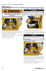
Operator Station
Gauge Display Panel
a.
Engine Oil Pressure Gauge
The engine oil pressure gauge notifies the operator of
the oil pressure status. Refer to the engine manual for
operating pressure range.
b.
Engine Coolant Temperature Gauge
The engine coolant temperature gauge notifies the
operator of the engine coolant temperature in degrees
Fahrenheit (white markings) and Celsius (red markings).
c.
Hour Meter
The machine hour meter keeps track and lets the operator
know how long the machine has been operated. The
operator can utilize this meter and the maintenance
chart to maximise the life of the machine, and maintain
machine performance.
Operator Switch Panel
d.
Ignition Switch
The ignition switch starts and stops the engine, as well
as providing power to the machine. When the ignition
key is turned counter clockwise, it will activate the glow
plugs. The glow plugs assist the engine when starting
in cold climates, see the engine manual for detailed
instructions on using the glow plugs.
Do Not cycle the glow plugs for more than 20 seconds.
Refer to the engine manual for temperature/time table
for glow plug cycle times.
e.
Differential Lock Switch
The differential lock switch allows the operator to engage
or disengage the axles to gain more traction. When the
differential lock is engaged the machine will be more
harsh on softer terrain and be harder to maneuver.
f.
Work Light Switch
The work light switch activates the front and rear work
lights.
g.
Park Brake Switch
The parking brake switch engages and disengages the
parking brake. The parking brake is required to be on
(switch illuminated) when starting the engine.
Note: When dismounting the machine be sure to set
the parking brake.
h.
Auxiliary Flow Switch
The auxiliary flow switch changes the direction of flow
through the quick couplers. The flow switch controls
the direction of flow but is activated by the buttons
located on the joystick. Depending on user preference
and attachment the proper setting can be achieved.
Side Control Console and Joystick
i.
Throttle Lever
The throttle lever controls the engine speed. The farther
forward the lever is pushed the faster the engine runs,
and the farther back the lever is pushed the slower the
engine runs.
j.
Auxiliary Control Buttons
The auxiliary control buttons activate hydraulic flow
through the quick couplers and to the attachment. The
commands can be changed depending on the attachment
and user preference. The
Auxiliary Flow Switch
(h)and
the control buttons work in conjunction to accommodate
multiple attachments and functions.
Operation
NOTICE
DO NOT leave machine unattended while running.
Stay at the operator station until the engine is
completely shut off and any attachments have
come to a complete stop. Remove key when done.
c
a
b
d
e
f
g
h
j
k
l
i
NOTICE
NEVER under any circumstance use fluid starting
aids with this machine. Using starting aids other
than the glow plugs will cause catastrophic engine
failure that is not covered by any warranty.


