background image

If the appliance is installed where the temporary hardness of the water is high, 

say over 150 ppm (as defined by BS 7593 1993 Table 2), the fitting of an in line 

scale inhibitor is required. This must be comply with the requirements of the local 

water company. 
Devices capable of preventing the flow of expansion water: e.g. non return valves 

and/or  loose  -  jumpered  stop  cocks  should  not  be  fitted  unless  separate 

arrangements are made for expansion water. 
If a non-return valve is fitted in the incoming water supply - e.g. in line with scale 

inhibitor then a D.H.W. expansion vessel MUST be obtained and fitted. 


4.8 INSTALLATION IN A BATHROOM 

The appliance is rated IPX4D 
The  boiler  may  be  installed  in  any  room  or  internal  space,  although  particular 

attention  is  drawn  to  the  requirements  of  the  current  IEE  (BS.7671)  Wiring 

Regulations  and,  in  Scotland,  the  electrical  provisions  of  the  building  regulations 

applicable  in  Scotland,  with  respect  to  the  installation  of  the  boiler  in  a  room  or 

internal space containing a bath or shower. For IE reference should be made to 

the current ETCI rules for electrical installations and I.S. 8 13:2002 

If the appliance is to be installed in a room containing a bath or shower then the 

appliance  can  be  installed  in  Zones  1  &  2,  as  detailed  in  BS.  7671.  Although 

consideration must also be given when fitting boilers within bathrooms to adhere 

to the current gas safety regulations.


19

Summary of Contents for 24CPM

Page 1: ...tput Central Heating Output Morco 24CPM LPG 26kW 24kW Morco 30CPM LPG 31kW 30kW Morco 24CPM Nat Gas 26kW 24kW Morco 30CPM Nat Gas 31kW 30kW EC TYPE EXAMINATION CERTIFICATE 177208 MORCO PRODUCTS LTD Morco House Riverview Road Beverley East Yorkshire HU17 OLD Tel 01482 325456 Fax 01482 212869 www morcoproducts co uk __ _ HEATING HOT WATER ____ ...

Page 2: ......

Page 3: ...ting CH and instantaneous hot water DHW The boiler can be set to work in a number of ways DHW supply only CH supply only Both CH and DHW supply The temperature of the CH and DHW supply can be set by using the knobs on the control panel DHW Comfort Mode The boiler has a Comfort Mode for hot water delivery only that can be selected on the front panel In this mode the boiler learns your hot water req...

Page 4: ...1 On off switch 2 LCD display panel and yellow status LEOs 3 Central heating temperature control knob 4 Domestic hot water temperature control knob 5 Central heating pressure test button 6 Reset push button burner LED 4 ...

Page 5: ...is active status LED DHW is ON Setpoint mode LCD display shows target CRJDHW temperature when adjusting CHIDHW control knobs Left dot is flashing After I0 seconds display shows actual CH Temperature Pressure mode CH water pressure bar can be seen on the LCD display by pressing the pressure test button It remains active for I0 seconds Comfort mode If comfort mode is active status LED Comfort is ON ...

Page 6: ...conds 3 The DHW supply can be switched off by turning the knob fully anti clockwise Comfort ECO Mode Selection 5 CH Pressure test button t Hot Water OFF Hot Water ON MIN COMFORT This is used to see what pressure is held in the CH circuit it should read between1 0 1 4 bar In order to see the pressure on the LCD display push the button The value will be displayed for approximately 10 seconds 6 Reset...

Page 7: ...ot water If the shower is in use and a kitchen tap is opened virtually all the hot water will be diverted to the kitchen as it offers the least resistance If an outlet is too restrictive it will slow down the flow rate and increase the temperature For example ensure the shower head is free from blockages caused by scale If a tap or shower head is too restrictive due to a fault or blockage the flow...

Page 8: ...maged turn off the appliance and consult your installer or service engineer If it is known or suspected that a fault exists on the appliance it MUST NOT be used until the fault has been rectified by a competent Gas Safe Registered Engineer THERMOSTATS TIMERS PROGRAMMERS This appliance may be fitted with one of the above devices to control the central heating function in the home These devices may ...

Page 9: ...e a more complex route between the boiler and the outside of the dwelling The main printed circuit board provides all the functionality and safety features for the boiler The board operates the gas valve fan pump 3 way valve and flame supervision The safety systems built into your appliance provide entire safety for you and your appliance The safety systems are Flue Gas Over heat Safety System 105...

Page 10: ...or immersion type 9 CH return NTC sensor surface type 10 DHW tlow turbine 11 Air I gas mixer box 10 12 Igniter 13 Ignition electrodes 14 Ionization electrode 15 Flue gas NTC sensor 16 Hydraulic circuit return manifold 17 Automatic air vent 18 Air inlet pipe 19 Expansion vessel 7 litres 20 Siphon Condensate Trap 21 Plate heat exchanger 22 Thermal cut off 160 C ...

Page 11: ...Domestic Hot Water Min Flow Rate For Activating 3 3 Jtr min Max Flow Rate 12 t JI c 14 t 32 C Itrimin Flow rate at 35 C temp rise 10 6 12 7 ltr min Min Operating Pressure 0 2 0 2 bar Max Operating Pressure 7 7 bar Set Temperature Range 35 60 35 60 oc Central Heating 0 8 0 8 Min Operating Pressure bar Max Operating Pressure 3 3 bar Set Temperature Range 30 80 30 80 oc General Electrical Supply 230V...

Page 12: ...ications General Power supply range standard 195 253 VAC Power supply frequency 50Hz Working temperature range 0 oc 60 oc Fusing 4A Inputs Water pressure switch 0 5 2 5 Vde 0 0 4 0 bar DHW flow turbine Max 14 1 min CH flow NTC sensor 10 k0hm 25 C CH return NTC sensor 10 k0hm 25 C Flue gas NTC sensor 10 k0hm 25 oc Thermal cut off 160 oc Room thermostat 24VDC Ionization current min 11 lA Outputs Gas...

Page 13: ...13 30 sec 3 MIN ...

Page 14: ...ectrode 8 230VAC Fan 9 230 VAC 3 way divertar valve 10 PC communication e Bus port 12 CH ratum NTC sensor 13 CH flow NTC sensor 14 CUI off 160 C 15 Flue gas NTC sensor 16 PWM Fan control 17 Water pressure sensor 18 DHW Flow turbine 19 Boiler chip card BCC port 20 Fuse4A 21 Power switch 22 CH potentiometer 23 DHW potentlonmeter 24 Reset button 25 Flame LED blue 26 Error LED red 27 Connector MICS20 ...

Page 15: ...nt dwellings BSEN721 Leisure accommodation vehicles ventilation requirements BSEN 1949 Installation of LPG System for Habitational Purposes in Leisure Accommodation Vehicles For Park Home installation refer to BS3632 Specifications for Residential Park Homes BS5440 Flueing and Ventilation IMPORTANT Manufactures instructions must NOT be taken in any way as over riding statutory regulations 4 1 BOIL...

Page 16: ...etc 300mm Adjacent to an opening fixed vent windows etc 300mm Below gutters 75mm Below eaves 200mm From a vertical drain pipe or soil pipe 75mm From an internal or external corner 300mm Vertically from a terminal on the same wall 1500mm Horizontally from a terminal on the same wall 300mm For domestic and Park Home applications please refer to BS5440 4 3 MINIMUM CLEARANCES Minimum clearances of 25m...

Page 17: ... park home is designed so that no pressure drop occurs No more that 3 m of 15mm pipe should be used Where the supply exceeds 3 m the pipe should be suitably sized only reducing to 15mm before the boil er A full bore isolation cock must be fitted in the supply close to the boiler or use Marco part number FW0391 If using bottled propane the bottle size must be taken account of The complete installat...

Page 18: ...eturn pipe as close as possible to the appliance If an extra vessel is required ensure that the total capacity of both vessels is adequate If the pressure display on the boiler control panel indicates 2 2 bar or greater when the appliance is at maximum temperature with all radiators in circulation an extra expansion vessel is required Pressure Relief Valve A pressure relief valve set 3 bar 43 5psi...

Page 19: ...4 8 INSTALLATION IN A BATHROOM The appliance is rated IPX4D The boiler may be installed in any room or internal space although particular attention is drawn to the requirements of the current IEE BS 7671 Wiring Regulations and in Scotland the electrical provisions of the building regulations applicable in Scotland with respect to the installation of the boiler in a room or internal space containin...

Page 20: ...20 ...

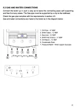
Page 21: ...must be supported by a clip to the bulkhead Check the gas pipe complies with the requirements in section 4 5 Gas and water connections are made to the boiler as in the diagram below I CD 0 171 2 3 0 4 1 CH Flow BSP 2 DHW Outlet BSP 3 Gas Inlet BSP 4 DHW Inlet mains BSP 5 CH Return BSP 6 Condensate Drain 7 Pressure Relief 15mm copper stub pipe 0 7 0 5 21 ...

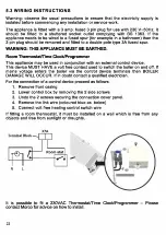
Page 22: ... external control device This device MUST HAVE a volt free contact used to switch the boiler on and off If mains voltage enters the boiler via the control device terminals then BOILER DAMAGE WILL OCCUR If in doubt contact a qualified electrician For the connection of a control device proceed as follows 1 Remove front casing 2 Lower control box by removing the 2 side screws 3 Undo the 2 screws secu...

Page 23: ...th required The flue must be fitted with a 2 or 3 downwards incline towards the boiler to ensure condense flows back into the boiler In cold or humid weather water vapour in the flue gas may condense when leaving the flue terminal Care must be taken when locating the boiler to avoid pluming causing nuisance to the occupier of the adjacent property The installer must ensure that an adequate seal is...

Page 24: ...All horizontal pipes must be connected at a slight 2 or 3 degree downwards incline to ensure a good flow Before connecting the flue the condensate trap must be filled with water This is achieved by tipping 1 litre of water into the INNER flue terminal on top of the boiler as below This prevents the risk of products of combustion escaping into the dwelling Take care when filling the condensate trap...

Page 25: ...ate pipe 2 Section of pipe above or below ground 3 100mm diameter pipe 4 Bottom sealed 5 Limestone chippings 6 Two rows of 12mm holes at 25mm centres 1 y f J22 500 4 5 1 7 Minimum hole size 400mm deep x 300mm wide 0 0 AI 7 25 ...

Page 26: ...e supply inlet pressure to the boiler is correct for the type of gas used 6 2 DOMESTIC HOT WATER Turn on the mains cold water isolation valve Fill and vent the installation by turning on hot and cold water taps Make sure that there are no leaks in the installation 6 3 CENTRAL HEATING CIRCUIT GAS PRESSURE TEST POINT In order for the boiler to function correctly the pressure in the central heating c...

Page 27: ...xternally on top of the boiler AUTOMATIC AIR VENT Always ensure that both the caps on the automatic air vents are loose prior to commissioning 6 4 CONDENSATE TRAP Ensure the trap is full with 1 litre of water See 5 5 Ensure all connections are water tight and that the condensate discharge pipe is correctly installed see 5 6 6 5 FLUE CONNECTIONS Ensure that the flue has a fall of 2 3 degrees back t...

Page 28: ...CPM Unit Natural Gas max load 2 38 2 92 m hour Natural Gas min load 0 71 0 88 m hour Propane max load 1 77 2 17 kg hour Propane min load 0 64 0 77 kg hour If no meter is available or the boiler is on bottled gas then with the use of a flue gas analyser refer to gas valve adjustment in the chapter 7 6 8 INITIAL OPERATION Domestic hot water To turn on the boiler follow the user instructions at the f...

Page 29: ...neer should Give the users Instructions to the owner and emphasise their responsibilities under the Gas Safety Installation and Use Regulations 1998 Explain and demonstrate the lighting and shut down procedures Advise the owner on the efficient use of the system including the use and adjustment of all system controls for both D H W ana C H Advise the user of the precautions necessary to prevent da...

Page 30: ...e cover off the pins at the top of the boiler 7 2 Servicing Schedule Before commencing any service operation ISOLATE the mains electric supply and TURN OFF the gas supply at the main service cock Service the appliance by following the full procedure aetailed below 1 Run the boiler in DHW mode and CH mode and carry out a pre service check noting any operational faults 2 Check the combustion perform...

Page 31: ...the inside of the tubes with a soft brush Do not brush the insulation at the rear check the combustion chamber insulation panels for damage and replace if necessary a Remove the burner injector gas restrictor lnspect the injector for blockage or damage and clean replace as necessary 9 Remove the condensate trap bottom cleaning nut Drain clean as necessary Important Notes In order to carry out serv...

Page 32: ... boiler at minimum load see section 7 4 Service Mode Be sure that boiler is running at minimum load minimum fan speed Wait approximately 4 minutes for the stabilization of the values Check the C02 value against the Setting Values Table below If the C02 value is not in the range 0 2 gas valve adjustment is necessary Turn the offset adjustment screw with 2 5 mm allen key clockwise in direction ve to...

Page 33: ...n at the minimum load To operate the boiler at the maxmum load turn the CH knob to the off position and back again to the service mode position within 3 seconds If the CH knob stays in off position the main board will cancel the service mode The status LED Service will blink to indicate the maximum load Service mode will be inactive after 10 minutes It is possible cancel the soft start function by...

Page 34: ...m built into their printed circuit board Should a fault for safety related or other reasons occur then the boiler will failsafe by locking out which is indicated by the red LED on the control panel The fault can be identified by the code in the LCD display The electronic failsafe is also backed by a mechanical means of protection should the electronics fail to detect a fault These mechanical forms...

Page 35: ...p fuse PCB Lack ofcirculation Check Lockout flue gas overheat Flow Return isolation valves are open 01 Ful1 TRV system have a by pass The flue gas sensor sensed By pass settings over 105 C Pump failure or set to maximum 3 setting I Faulty Flue gas NTC or wire detached Lack of circulation Check Lockout boiler overheat j Flow Return isolation valves are open 01 Full TRV systems have a by pass CH flo...

Page 36: ...36 ...

Page 37: ...s caused by a defective electrical supply Damage or failure caused by insect contamination or blocked water filters Loss off pressure within the heating system not caused directly by the boiler Incorrect operation of the boiler caused by defective outlets such as thermostatic mixers or mono block mixer taps Damage caused by unauthaurised modifications to the boiler from original spec ifications Fo...

Reviews: