3
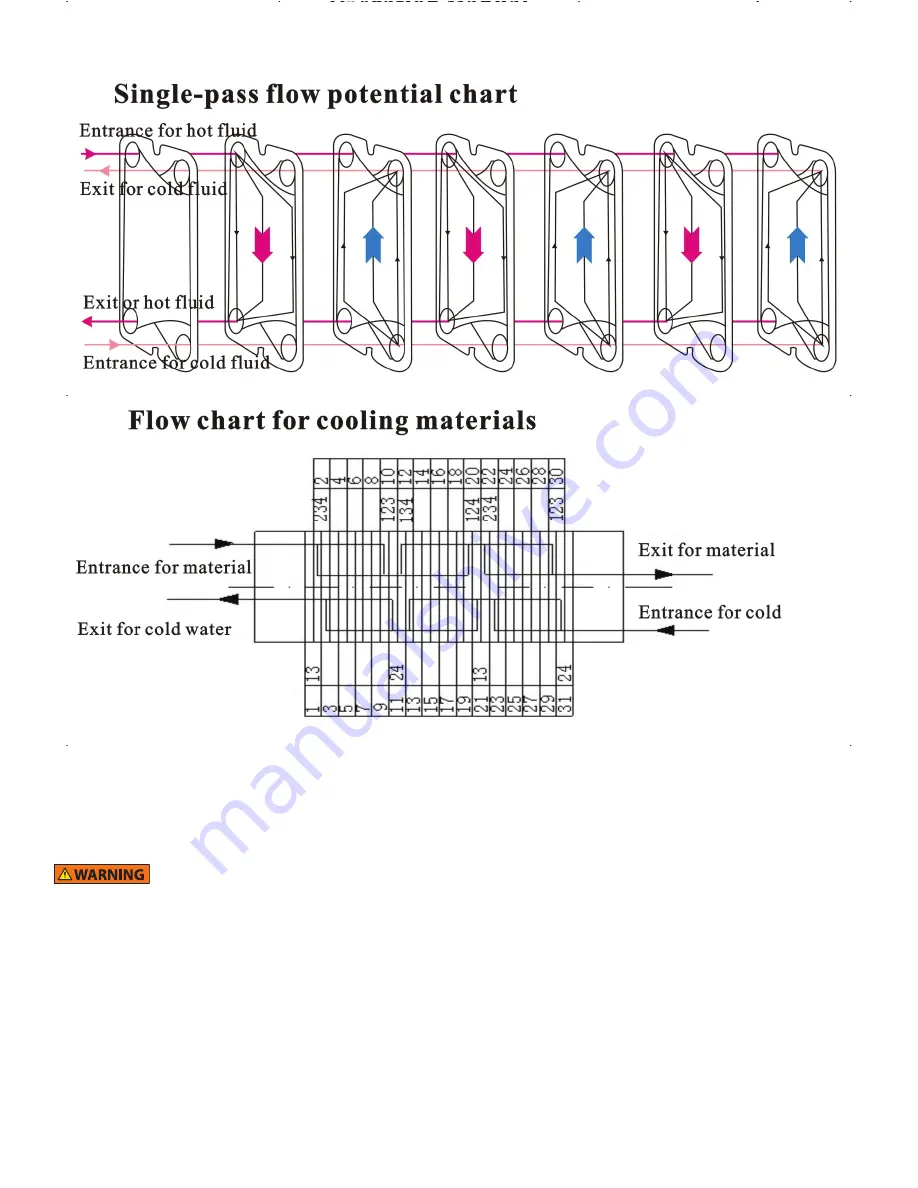
Flow Chart of Plate Exchanger:
F. Installation
1.
There are lifting eyes on the two clamping panels. Lifting ropes should NOT be attached to the connecting pipes, plate guides, or plates.
2.
There should be 3 feet of clearance around the exchanger for maintenance.
G. Assembly
•
Failure to follow proper assembly will result in poor performance of the heat exchanger.
•
Nuts not torqued sufficiently can cause the heat exchanger to leak.
TIP
:
The connections for using the heat exchanger as a two-stage cooling system are labeled on the unit. The product flow is marked wort
in and wort out. The stage one path is marked water in and water out. The stage two path is marked as glycol in and glycol out. Proper
connection is required for proper cooling. This is not the only way the heat exchanger can be used. i.e., wort could be circulated from the
mash, and hot liquor could be circulated through the water pathway to use the heat exchanger to increase wort temperature.
1.
Make the six connections that connect the heat exchanger to product, water, and chilled liquor.
2.
An optional vent valve can be used at the exit to bleed air from the heat exchanger. It is important that no trapped air remains in the
heat exchanger during operation.
3.
It is important to keep the passageways clean. Debris should be kept out of the heat exchanger to avoid blockage.
4.
In some applications, you may need to include a filter at the entrance and exit to avoid particles or microfibers in the media.
TIP
:
If there is no glycol available the stages can be connected in series.


