background image

MOREHOUSE INSTRUMENT COMPANY INC. MODEL 4215 PLUS V5.0.6 

Model 4215 Plus 


Pg. 55 PUB.6396-02 

Morehouse Instrument Company, Inc. 


Tel: (717) 843–0081 

APPENDIX A – MODEL 4215 PLUS SPECIFICATIONS 


Transducer Interface 


Excitation 

5VDC or 10VDC software/auto selectable 

Current Drive 

180mA at 5VDC or 10VDC 

Push Button Shunt 

Yes 

Internal Shunt Resistor 

1 standard, 2 optional.  Rear panel selectable 

Calibration Method 

Shunt, mV/V, Known Load 

Push Button Tare 

100% of range--display and analog output 

Sensitivity Adjust 

1 mV/V to 4.5 mV/V 

Accuracy 

0.01% of full scale +/- 1 digital count 

CMRR 

115 dB 


Additional Transducer Channel 


Auxiliary Channel 

Optional 


D/A Analog Output 


Full Scale Output 

+/- 10VDC n/- 0.5VDC 

Linearity 

0.02% of full scale 

Scaling 

Gain and offset selected by software. 

Frequency Response 

Approx. 15 Hz (plus filtering) 

Output Source 

Any displayed quantity 

Output Channels 

1 std, 2 optional 


Direct Analog Output 


Full Scale Output 

-/+ 8.14VDC +/- 0.25VDC 

Linearity 

0.02% of full scale 

Scaling 

Fixed with no tare, transducer channel only 

Frequency Response 

Approx. 1.5 kHz 


Peak/Hold 


Peak/Valley/Hold 

Digital 1/60 second capture 


Summary of Contents for 4215 Plus

Page 1: ...Model 4215 Plus Smart Indicators Morehouse Instrument Company Inc 1742 Sixth Ave York PA 17403 USA Tel 717 843 0081 Fax 717 846 4193 www mhforce com ...

Page 2: ...which is A Not reported to the company within the applicable warranty period or B Due to misapplication modification disassembly abuse improper installation by others abnormal conditions of temperature dirt or corrosive matter or C Due to operation either intentional or otherwise above rated capacities or in an otherwise improper manner The company believes that the information in this manual is a...

Page 3: ...PHANUMERICAL DATA 13 USER DATA ENTRY 13 Base Area Entry 13 Base Length 13 ANALOG OUTPUT 13 SENSOR OPTIONS 14 CALIBRATION 15 Cal Check 15 Two Point mV V 15 Five Point mV V 16 Two Pt Five Pt Data Cal 16 Shunt Cal 16 Polynomial Cal 17 Counts Inch 17 LIMITERS 17 SYSTEM OPTIONS 18 Printer Baud 19 Auto Identify 19 AutoID Annunciator 19 Auto Zero Channel 19 Com Address 19 Com Baudrate 19 Com Line Feed 19...

Page 4: ... COMMAND U 33 User Data View Command UV 33 User Data Area Command UA 34 User Data Length Command UL 34 ANALOG OUTPUT COMMAND A 34 Analog Output View Command AV 34 Analog Output Set Command AS 35 SENSOR COMMAND S 35 Sensor View Command SV 35 Sensor Select Command SS 36 Sensor Delete Command SD 36 Sensor View Calibration Points Command SZ 37 CALIBRATION COMMAND C 37 Calibration Check Command CC 38 C...

Page 5: ...2 Display Second Line Text DT 52 SYSTEM CALIBRATION MODE 53 FORCE AVERAGING OPTIONAL 54 APPENDIX A MODEL 4215 PLUS SPECIFICATIONS 55 APPENDIX B CABLES AND CONNECTORS 58 SENSOR CONNECTORS 58 SERIAL PORT CONNECTOR 58 DIGITAL I O CONNECTOR 60 CHART REC CONNECTOR 61 USB CONNECTOR 61 PRECISION SHUNT CALIBRATION RESISTORS 62 APPLICATION NOTE 63 MAKE YOUR OWN PLUG AND PLAY LOAD CELL SYSTEM AND ELIMINATE ...

Page 6: ...d force klb kilo Newtons kN metric tons t milli volt per Volt mVV or gram force gf User defined Base Area for Psi Pounds per square inch and MPa MegaPascals Tare at any time Capture the load peak valley gross polynomial and optional average Displayed in pound force lbf kilogram force kgf Newtons N Pounds per square inch Psi MegaPascals MPa kilo pound force Klb kilo Newtons kN metric tons t milli v...

Page 7: ...llows you to choose between two values used for the Shunt Calibration so there is no need to open the unit Up to Two Channels of Analog Output of any signal Load Peak Valley Position and Velocity with user defined scale factor and offset Large buffered 10 00 Volt output Remote operation using ASCII Commands set via the Serial RS 232 RS 485 port or the USB port Back panel Digital Inputs for Tare Pe...

Page 8: ... will see a sequence of 2 messages appear on the front display For example Message Meaning 1 Morehouse X Y Z This is the version number 2 Serial 12345 Option 4653056 This is the serial number This is the option number Message 1 will be displayed for roughly 4 seconds while message 2 will be displayed for about 2 seconds After that the front panel display will start showing the current readings fro...

Page 9: ...ce Kilo Newtons Metric Tons mV V Gram Force Peak A PeakA Pound Force Kilogram Force Newtons Psi MegaPascals Kilo Pound Force Kilo Newtons Metric Tons mV V Gram Force Valley A VallA Pound Force Kilogram Force Newtons Psi MegaPascals Kilo Pound Force Kilo Newtons Metric Tons mV V Gram Force Load B LoadB Pound Force Kilogram Force Newtons Psi MegaPascals Kilo Pound Force Kilo Newtons Metric Tons mV V...

Page 10: ...elect the currently displayed option within a submenu Pressing Esc will return to the previous menu Run Mode without selecting anything Note All menu lists on the Model 4215 Plus start with the symbol and that the Esc button will always back out of a menu without making any changes Each submenu adds an additional to the title Item Button The Item button cycles through the List of different Items t...

Page 11: ...peated presses of the View button will now switch back and forth between Load in Lbf and Peak in Psi with a single button push If you choose to have the second line show a display then the View button toggles between the Lines The activated Line to which all other buttons will apply will have a symbol to the left of it Print Hold Button The Print Hold button performs two functions that are user se...

Page 12: ...nly View Sensor Data Sensor Select Sensor Data Channel Sensor Delete Sensor Data Sensor View Cal Points Sensor View Cal mVV Gains Sensor View Tag ID Channel Calibration Cal Check Channel Two Point mV V Channel Data input Five Point mV V Channel Data input Two Pt Data Cal Channel Data input Five Pt Data Cal Channel Data input Shunt Channel Data input Polynomial Cal Channel Data input Counts Inch Li...

Page 13: ...u Items begin with the symbol and that all submenu Items begin with the symbol User Data Entry allows you to set any common math options such as the Base Area used to display Load in Psi or the Base Length used to display Position in percent Analog Output is used to select the Analog Channel Source and Scaling for the Analog Output Channels Sensor Select allows the user to manually select delete w...

Page 14: ...igit above the cursor Thus 12 34 becomes 11 34 Note that 0 will wrap around to 9 on numerical value entries only On alphanumerical entries 0 will wrap around to z Some data entry fields will include additional ASCII symbols to select from while scrolling with this button Plus and Minus both and at the same time This will change the sign of the number Thus 12 34 becomes 12 34 Note the cursor positi...

Page 15: ...ro analog voltage 0 0 volts Once you have entered these five 5 selections the Analog Output is setup Sensor Options The Sensor Options menu is used to view the current calibration data on each channel view all sensor data manually select Load Cell sensors for each channel or delete them view each sensors Cal points and mV V Gains and view tag ID data for each channel if present Use either the Left...

Page 16: ...nt you with a channel selection of either A or B once a channel is selected is will automatically begin running a Calibration Check on the Load Cell Sensor attached to Channel specified The Model 4215 Plus will measure the Shunt Value of the Load Cell and compare it to the Shunt Value that was recorded when the Load Cell was last calibrated The last Calibration Date for the Load Cell is displayed ...

Page 17: ...he Value of the First Mass The Mass 1 Ready message will wait while you physically apply the mass to the attached Load Cell Once the mass is applied press the Enter button When the Model 4215 Plus is reading the Load Cell it will display the Calibrating Mass 1 on line 1 and Reading on line 2 messages for about 10 seconds At this time it is important that the Masses are not disturbed since all the ...

Page 18: ... decimal value that is used while writing a value in scientific notation In the two examples of scientific notation depicted in the below example the mantissa is 1 2815 1 2815 E 02 or 1 2815 x102 Exponent relates to the exponential value used while writing a number in scientific notation In the two examples of scientific notation depicted in the above example the exponent is 2 When a degree of gre...

Page 19: ...e becomes less than the Set Point 8 Latching Limit Selecting Latching Off means that the Limit will be de activated automatically when the Source passes the Reset Point see next selection Selecting Latching On means that once the Limit is activated you must manually reset it using the Reset button If you select Latching On then the Limit Setup is done 9 Limit Reset Value This selection determines ...

Page 20: ...Mode The t will blink if a non recognized or non AutoID cell is attached If a recognized AutoID cell is attached the t will change from blinking to solid Auto Zero Channel The Auto Zero Channel Menu lets the user Enable or Disable Auto Zeroing for Load measurements on Channel A or Channel B When Enabled the Auto Zero Channel function will Tare the Load to Zero any time that it has remained within ...

Page 21: ...isplayed and printed These are listed in a submenu that works exactly like the Setup Mode Main Menu Filter Select There are two types of filters available on the Model 4215 Plus Type 1 and Type 2 Type 1 filters are good for removing most kinds of noise but may leave some jitter on the end digits Type 2 filters are more advanced filters that are optimized for the typical industrial environment Both...

Page 22: ...mber of decimal digits shown may be limited For example a 100 Lb Cell will allow 3 digits while a 1000 Lb Cell will only allow 2 digits Also if a number is too large to fit on the display some decimal digits may be dropped the display will Auto Range The number of digits shown for position data depends only on the number of counts per inch of the Encoder and is not affected by this setting Count B...

Page 23: ...ht of the decimal point This setting only effects the Displayed value if the least significant digit of the Counts per Inch falls outside the Max Position Decimal place For example If the Counts per Inch is set to 1000 while Pos Decimal is set to 4 the least significant digit effected will be 0 001 and the display will show 0 0010 If the counts per inch is set to 100000 and the Position Decimal is...

Page 24: ...tion of the Digital I O connector If you do not require isolation for your application you can use the 5 or 12 volt and GND available on the Digital I O Connector pins 24 26 These 4 inputs are called IN1 through IN4 and have the following standard functions IN1 Will Tare the Load to zero while it is in the ON State IN2 Will Reset the Peak and Valley measurements while it is in the ON State IN3 Wil...

Page 25: ...an communicate with the Model 4215 Plus via USB no driver is needed USB COMMUNICATIONS INFORMATION If using remote communications and the host PC cannot communicate with the Model 4215 Plus via USB USB Driver If the host PC cannot communicate with the Model 4215 Plus via USB install the USB driver USB drivers and updates may also be obtained from http www ftdichip com Drivers VCP htm Driver versio...

Page 26: ...f letters and or numbers such as the XYZ shown above o If the Command requires a number as one of its parameters the number must be followed by the pound sign Numbers that are less than one should include a leading zero so you should type 0 123 to enter one hundred twenty three thousandths Commands are not processed until a carriage return CR is sent Notes No Model 4215 Plus will respond to addres...

Page 27: ...tare peak vall pos Reset readings X Hold Data OPTIONAL T hold text Place text on display REMOTE RUN MODE COMMANDS The commands listed in this section mirror and in some cases extend the functions that are available from the front panel of the Model 4215 Plus when it is in Run Mode Each entry in this section will include the name of the Command followed by a short description that includes the comm...

Page 28: ...B 51 Peak AB 52 Vall AB These are the units for Load Peak and Valley 00 lbf 01 kgf 02 N 03 Psi 04 MPa 05 Klb 06 kN 07 t 08 mVV 09 gf 10 lbI 11 NM 12 OzI These are the units for Position 00 In 01 Cm 02 These are the units for Velocity 00 I M 01 C M Front Panel Display Command F This Command is used to set the front panel display of the Model 4215 Plus to a desired combination of Items and units The...

Page 29: ...s if you had pressed the View button Example User Entered 001FA Acknowledgment 001 Active Display shows Load A in lbf Other Display shows Vall A in lbf Front Panel Pointer Control to Line 1 F1 The Front Panel Pointer Control to Line 1 F1 assigns the View Pointer Control to display line 1 upper line of the display and shows what is on the display This allows the operator to know which line will be ...

Page 30: ...values that are being sent by a repeat 2 Command Note Item numbers specific to this command only shown in the Question Mark Command are 50 Cells AB 51 Peak AB and 52 Valley AB Example 1 User Entered 001V01021 Acknowledgment 1 001 Peak A 0 0111 N Example 2 User Entered 001V5000002 Acknowledgment 2 001 Load A 120 452 lbf Load B 0 05898 lbf 001 Load A 125 295 lbf Load B 0 24738 lbf 001 Load A 134 367...

Page 31: ... lbf Load B 22 5600 lbf Peak B 23 0000 lbf Vall B 0 00001 lbf Pos 3 500 In Vel 0 00000 I M Grs A 9 81467 lbf Grs B 8 51474 lbf Ch A B 0 05408 lbf Poly A 0 00000 lbf Poly B 0 00000 lbf Limits 0 0 0 1 Reset Tare Peak Valley and Position Command R This Command allows you to reset the Tare Peak Valley and Position readings The format is R tare A peak A valley A tare B peak B valley B position select W...

Page 32: ... displayed on the 1st character of the line to indicate that the unit is in Hold Mode Text Display Command T This Command allows you to put a line of text on the front panel display of the Model 4215 Plus The format is T text Where text is the message that you want to display The text is limited to the number of characters that can be shown on the front panel display This command is identical in f...

Page 33: ...r Volt M Number of Points Masses Calibrate by points M P1 mass 1 Calibration Mass 1 M P2 mass 2 Calibration Mass 2 M P3 mass 3 Calibration Mass 3 M P4 mass 4 Calibration Mass 4 M P5 mass 5 Calibration Mass 5 M P6 mass 6 Calibration Mass 6 optional M P7 mass 7 Calibration Mass 7 optional M P8 mass 8 Calibration Mass 8 optional M P9 mass 9 Calibration Mass 9 optional M PT mass 10 Calibration Mass 10...

Page 34: ... panel There are additional Commands that are for Remote use only If the optional Keylock is installed and locked you will not be able to alter the setup until the unit has been unlocked The acknowledgment from Model 4215 Plus will indicate this fact 001 Setup is Locked use Keylock to unlock User Data Entry Command U This Command is used to view or set the options in the user data entry menu namel...

Page 35: ...ommand UL is used to set the Base Length The format is UL number Example User Entered 001UL2 5 Acknowledgment 001 Base Length is 2 50000 inches Analog Output Command A This Command is used to view or set the Analog Output of the Model 4215 Plus There are two 2 subcommands Analog Output View AV Analog Output Set AS Analog Output View Command AV The Analog Output View Command AV has the format AV It...

Page 36: ... 0000 lbf Sensor Command S This Command is used to view or select calibration data from the list of calibrated Load Cells maintained by the Model 4215 Plus There are four 4 subcommands Sensor View SV Sensor Select SS Sensor Delete SD Sensor View Calibration Points Command SZ Sensor View Command SV The Sensor View Command SV has the format SV It returns information about the currently selected Load...

Page 37: ...hunt unused S N 110 4 00 lbf 4 00000 mV v 10 00 V Cal on Jan11 22 1 4440 lbfShunt unused S N 205 4 00 lbf 4 00000 mV v 5 00 V Cal on Jan11 22 1 4563 lbfShunt Ch B S N 210 4 00 lbf 4 00000 mV v 10 00 V Cal on Jan11 22 1 4439 lbfShunt Sensor Delete Command SD The Sensor Delete Command SD is used to remove the calibration data for a stored Load Cell from the list The format is SD serial number Exampl...

Page 38: ...E cancels a calibration that is underway Calibration by milli volt per Volt CV runs a one point calibration using the Load Cell milli volt per Volt constant Calibration by milli volt per Volt CMV5 runs a five point calibration using the Load Cell milli volt per Volt constant Calibration by Polynomial Equation CP runs a Polynomial calibration using a specified number of degrees and their associated...

Page 39: ... any method You must issue the CB Command before trying to calibrate by milli volt per Volt Masses or Shunt CV CM or CS While the Model 4215 Plus is being calibrated using the Remote Commands the front panel will show RS232 CAL STARTED Pressing the front panel Escape button Esc will cancel the calibration and issue a warning to the Remote Terminal If any Remote Commands other than Calibration Comm...

Page 40: ...cel a calibration that was started with the Calibrate Begin Command CB This format is CE Example User Entered 001CE Acknowledgment 001 Calibrate Command Canceled Calibration NOT Changed Calibrate by milli volt per Volt Command for One Point CV The Calibrate by milli volt per Volt Command for One Point CV is used to calibrate a Load Cell using its milli volt per Volt Calibration Constant You must h...

Page 41: ... Check Calibration will also be running at the end of the calibration and so it is important that the Load Cell is set at 0 or no masses when the final command is entered Example User Entered 001CMV5 Acknowledgment 001 Calibrate By mV Volt 5 Point Ready for Mass CMVM1 command Calibrate by Polynomial Equation CP The Calibrate by Polynomial Equation CP is used to calibrate a Load Cell using a polyno...

Page 42: ...0 mV v 5 00 V Cal on Jan01 18 0 0000 lbfShunt unused S N 110 4 00 lbf 4 00000 mV v 10 00 V Cal on Jan01 18 0 0000 lbfShunt Ch B S N 205 4 00 lbf 4 00000 mV v 5 00 V Cal on Jan01 18 0 0000 lbfShunt unused S N 210 4 00 lbf 4 00000 mV v 10 00 V Cal on Jan01 18 0 0000 lbfShunt Ch A S N 123456 1000 0 lbf 1000 00 mV v 10 00 V Cal on Jan11 22 1 4440 lbfShunt Calibrate by mV V Mass and mV V Volt Commands ...

Page 43: ... Ready for Mass value CMVM2 or CE command The unit will continue to prompt the user for mass and milli volt per Volt values until the fifth point has been entered Then the user will see the following acknowledgement 001 Calibrate mV V 5 Command entered Ready for Mass value CMVM0 or CE command The user must now enter the CMVM0 Command to finish the calibration Note that the Load Cell should have no...

Page 44: ...l 4215 Plus to read 10 seconds of data from the Load Cell These readings are averaged to obtain the first Calibration Mass Reading Be sure that you have placed the mass on the Load Cell before entering this command since reading will begin immediately The example uses 0 Lbf for the first Calibration Mass Example User Entered 001CMP10 Acknowledgment 001 Calibrate Mass 1 Command Reading 10 second de...

Page 45: ...lbfShunt Ch A S N 123456 1000 0 lbf 4 96103 mV v 4 96133 mV v 4 96127 mV v 4 96128 mV v 10 00 V Cal on Jan11 22 291 08 lbfShunt Calibrate by Shunt Command CS The Calibrate by Shunt Command CS is used to calibrate the Load Cell using the Shunt Calibration Factor expressed in pounds This Command will only function if you have already issued the Calibration Begin Command CB Note that the Load Cell sh...

Page 46: ...IS Allows you to change the current setting of the Encoder Counts per inch Constant Example User Entered 001CIS64000 Acknowledgment 001 Encoder is 64000 Counts per Inch Limits Command L This Command allows you to view or set the 4 contact closure limit switches on the Model 4215 Plus There are four 4 subcommands Limit View LiV Limit Set LiS Limit Setup Escape LE Limit Reset LiR In the above list o...

Page 47: ...lly closed The Enable should be set to 0 for disabled or 1 for Enabled If the limit is disabled the rest of this command may be omitted see example 3 The Item and Unit Number indicate which signal is to drive the limit and the values can be found with the Question Mark command The Set Point Number indicates the signal level at which the limit is to be activated The or sign indicates whether you wa...

Page 48: ...red 001LE Acknowledgment 001 Limiter Setup Command Canceled Limit Reset Command LiR The Limit Reset Command LiR is used to manually reset a latching limit that has been activated The format is L limit number R Example User Entered 001L1R Acknowledgment 001 Reset Limiter 1 System Options Command O The System Options Command has nine 9 subcommands that are used to view or set the options that appear...

Page 49: ...ist of the current settings of all the System Options The format is OV Example User Entered 001OV Acknowledgment 001 Printer Baud Rate is 230 4k Auto Identify is off Auto Identify Annunciator is off Auto Tare is on Auto Zero Channel A is off Auto Zero Channel B is off Com Address is 001 Com Baud Rate is 9600 Com Line Feed is on Retain Tare is off RS232 End of Transmission Character is off Option P...

Page 50: ...to Zeroing off and on respectively Example User Entered 001OZA1 Acknowledgment 001 Auto Zero Channel A is on Auto Zero Channel B is off Option Com Address Command OA The Option Com Address Command OA is used to change the communications address assigned to this unit The format is OA new address Note The valid addresses are 1 through 254 Example User Entered 001OA3 Acknowledgment 003 Com Address is...

Page 51: ...Enabled the Tare Values are retained until this option is disabled Disabling the Tare Retention Option resets the Tare values for both channels to 0 Example User Entered 001OT1 Acknowledgment 001 Retain Tare is on Option Hold Freeze OH The Option Hold Freeze Command OH sets the usage of the Print Hold button When followed by a 0 the button is set to Print when pushed OH0 when followed by a 1 the b...

Page 52: ...I Level 1 Filter Window A is On Filter Window A 1 0000 lbf Filter Window B is Off Channel A shows 5 decimal digits Channel B shows 5 decimal digits Channel A counts by 1 Channel B counts by 1 Second line shows display Line 2 Message Stress Test Ready Velocity Filter Level is 1 Position shows 5 decimal digits Velocity shows 5 decimal digits Display Filter Command DF The Display Filter Command DF se...

Page 53: ...econd Line Command D2 is used to set the second line to be blank or to show the Limit status The format is D2 B L D or T Where B makes the line blank L makes the line show the Limit status D makes the line show another display and T makes the line show text Example User Entered 001D2B Acknowledgment 001 Second Line set to Blank Display Second Line Text DT The Display Second Line Text Command DT is...

Page 54: ... if a 2 channel unit otherwise performs exactly like Ch A Board Cal Bcal Scale Values Displays the board calibration scale values DAC Calibration Used to calibrate DAC if option is present DAC Cal Scale Vals Displays the DAC calibration scale values if applicable A five minute warm up period with the milli volt per Volt reference attached is recommended at this time if the milli volt per Volt refe...

Page 55: ...calculated and displayed on Channel A and the Item Avg B refers to the Average Force measured calculated and displayed on Channel B Opening the Digital Input Circuit will stop the averaging The final Average Value will remain on the display until the input is again activated or the unit is powered down If you do not require isolation for your application you can use the 12 Volt Source and an avail...

Page 56: ...e display and analog output Sensitivity Adjust 1 mV V to 4 5 mV V Accuracy 0 01 of full scale 1 digital count CMRR 115 dB Additional Transducer Channel Auxiliary Channel Optional D A Analog Output Full Scale Output 10VDC nominal 0 5VDC Linearity 0 02 of full scale Scaling Gain and offset selected by software Frequency Response Approx 15 Hz plus filtering Output Source Any displayed quantity Output...

Page 57: ...Quad Limits Source Any displayed quantity Serial Interface RS 232 Serial Setup Output Standard RS 485 Serial Setup Output Optional Multi drop RS 232 Optional USB Optional Printing Optional Interface Type Serial Quantities Printed All displayed Items Encoder Position Channel Optional Encoder Type Quadrature 4X number of lines Excitation 12VDC std 5VDC optional Interface Single ended or differential...

Page 58: ...ers 8 software selectable Electrical Characteristics Power Requirements 115 VAC 60 Hz Optional 230 VAC 50 Hz Fuse Requirements 115 VAC Fuse T 0 315A 250V 230 VAC Fuse T 0 160A 250V Power Consumption 12 W unloaded Transducer Excitation Current Shutdown mode when shorted to ground Absolute Max Transducer Input 30VDC without damage Physical Characteristics Package Size 10 0 W X 3 0 H X 10 5 D 25 4 x ...

Page 59: ...e System Options Menu 2 The printer uses RS 422 differential signaling on pins 5 6 and 10 Baud rate for the printer is selectable using the Printer Baud entry on the System Options Menu 3 Pins 7 8 14 and 15 are used for RS 485 ASCII Command set communications Use 8 data bits no parity 1 stop and set the baud rate using the Com Baud Rate entry on the System Options Menu DB9 Female Pin Signal 1 EXCI...

Page 60: ... 26 Female Pin Signal 1 LIM 1 A1 2 LIM 1 B1 3 LIM 2 A 4 LIM 2 B 5 LIM 3 A 6 LIM 3 B 7 LIM 4 A 8 LIM 4 B 9 ISO IN 1 HI2 10 ISO IN 1 LO2 11 ISO IN 2 HI 12 ISO IN 2 LO 13 ISO IN 3 HI 14 ISO IN 3 LO 15 ISO IN 4 HI 16 ISO IN 4 LO 17 KEYLOCK3 18 GND 19 ENCODER CHA L4 20 ENCODER CHA 21 GND 22 ENCODER CHB L4 23 ENCODER CHB 24 GND 25 GND 26 12VDC 5VDC optional4 ...

Page 61: ...ese inputs may be operated using the 12VDC supplied on pin 26 and the GND on pin 24 3 The keylock input will be in the unlocked state if left unconnected Tie this pin to GND to lock it When locked the setup of the Model 4215 Plus cannot be changed you cannot enter Setup Mode 4 The encoder inputs are intended for use with a 12VDC Quadrature Encoder For single ended signaling use the CHA and CHB pin...

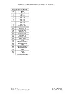
Page 62: ...h the menus 2 The HIGH BANDWIDTH OUT2 is a buffered analog output permanently connected to the Load Cell Channel 3 If the 4 20mA Option is purchased DB9 Male Pin Signal 2 ANALOG OUT1 3 ANALOG GND 4 HIGH BANDWIDTH OUT2 CHANNEL A 5 4 20mA OUT3 CHANNEL A 6 2nd ANALOG OUT1 Optional 7 4 20mA OUT3 CHANNEL B 8 HIGH BANDWIDTH OUT2 CHANNEL B 9 No Connect USB Connector Pin Name Description 1 VCC 5VDC 2 D Da...

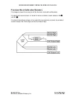
Page 63: ...cision Shunt Calibration Resistors This diagram shows the connection of the Precision Internal Shunt Resistors The back panel switch shown to the left of the two resistors selects between 30 KΩ and 60 KΩ The Shunt Check Relay shown to the right of the two resistors connects the selected resistor between the Excite High and the Cell Output High ...

Page 64: ... implemented simply on any Load Cell and when connected to the Model 4215 Plus Smart Indicator or Model 4325 CellMite Embedded Digital Signal Conditioner becomes transparent to the user Multi Load Cell multi Instrument matched pair calibrations are also supported This can be a critical advantage in precision applications such as field calibration services With the TEDS Tag system a small and inexp...

Page 65: ... making it easy to fit into a cable hood or load cell housing Figure 1 Electronic Identification Chip Both the Model 4215 Plus and CellMite are connected to Load Cells via a DB9 connector with identical pinouts The Electronic Identification Chip does not interfere with the Load Cell signals Figure 2 shows the interconnection of the DS2401 tag identification chip with the DB9 sensor connector on th...

Page 66: ...o the Load Cell and access to the Load Cell cable is restricted an In Line Tag Identification Module can be simply constructed Figure 4 shows how a straight through In Line Cable Adaptor can incorporate the DS2401 Electronic Tag Chip The protective hood has been removed for clarity In this application the cable adapter is physically placed in series with the Load Cell cable before it is plugged in...

Page 67: ...f the TEDS Tag Load Cell and matches it with its calibration data From this point forward the system is completely plug and play Typical startup is now 1 Plug Load Cell into the Instrument 2 Turn on the power After they ve been initially calibrated on the Instrument changing Cells is done by simply plugging the new Cell into the Instrument and turning on the power Figure 5 shows the front panel of...

Reviews: