Universal Calibrating Machine
(UCM) Manual
(PM-5201)
Morehouse Instrument Company, Inc.
1742 Sixth Ave., York, PA 17403-2675 USA
Phone: (717) 843-0081
www.mhforce.com
Page 23
Rev. 11/2021
Check for clearance between the tension member and the underside of the lower machine platen. This clear
-
ance should be approximately 1/8 inch. If the clearance is greater than 1/8 inch, then raise the lower yoke
platen as needed. Always check to be sure there is clearance between the test instrument and its adapters and
the lower machine platen.
Caution: Always be sure any fasteners supplied or used with tension members are fully engaged.
4.4 Hand Pump Operation
The hand pump supplied with the calibrating machine is a dual-volume design based on a double-diameter
piston. On the side of the pump is a valve rod (Figure 5) with a round handle. With the rod pulled out, the full
diameter of the piston is effective for large volume, low pressure pumping; with the rod pushed in, the re
-
duced diameter is effective for high pressure with a minimum of pumping effort.
Caution: Before pushing the rod in, release any downward pressure applied to the hand lever.
During pump operation, the fill plug on the upper right side of the pump body should be open about two turns
to serve as a reservoir vent. Operation of the hand pump is entirely conventional. Operating the hand lever
causes oil to be pumped from the reservoir to the outlets. When the relief valve is closed (handle rotated
toward the hose connection on the pump body), pressure is developed within the pump. Opening this valve
relieves the oil back to the reservoir. In operating the relief valve, use modest pressure on the handle - just
enough to prevent leakage.
The auxiliary screw piston (Vernier piston) is a small-displacement precision piston. After pressure has been
built up by means of the hand lever to obtain the approximate force desired, rotate the hand wheel to operate
the Vernier piston and maintain a precise force. We recommend that the Vernier piston adjustment be kept at
its mid-position of travel to allow small increments of force to be increased or decreased. Experience will dic
-
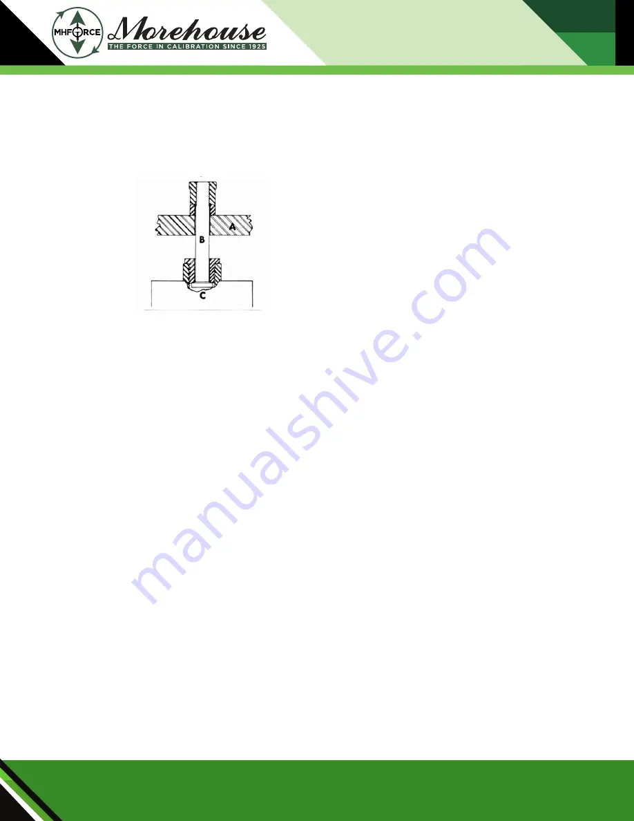
Figure 14:
A) Lower Yoke Platen
B) Tension Member
C) Test Instrument
Figure 14 shows the method of connecting a tension member (B) between the test instrument (C) and the low
-
er yoke platen (A). The test instrument is connected to the lower machine platen in a similar fashion.


