background image

▒▓


Monitor Series


Vital signs Monitor instruction Manual 


- 6 - 

as  an  adjunct  in  patient  assessment.  It  must  be  used  in  conjunction  with  clinical  signs  and 
symptoms. 

!

  Prolonged  use  or  the  patient’s  condition  may  require  changing  the  sensor  site  periodically. 

The site must be checked at least every four hours to ensure adequate adhesion, circulation, 
skin  integrity  and  correct  optical  alignment.  If  the  circulatory  condition  or  skin  integrity  is 
compromised, the sensor should be applied to a different site.   

!

  Use  only  the  battery,  power  cable  and  accessories  appointed  by  manufacturer,  as  other 

accessories may cause improper performance or dangers. 

!

  Connect the monitor to a three-wire, grounded, hospital-grade receptacle if necessary.. 

!

  By replacing the fuse, please use the safety fuse of the same type and rated fuse. 

!

  When  connecting  the  monitor  to  any  instrument,  verify  proper  operation  before  clinical  use. 

Refer to the other device’s manual for full instructions. Accessory equipment connected to the 
monitors  data  interface  must  be  certified  according  to  IEC  Standard  60601-1  for  electro 
medical equipment. All combinations of equipment must be in compliance with IEC Standard 
61601-1-1  systems  requirements.  To  avoid  potentially  hazardous  leakage  currents,  always 
check the summation of leakage currents when several item of equipment are interconnected. 

!

  Before use the equipment, inspect whether all the cables are in good condition, the damaged 

cables and connectors must be replaced. Operator should examine whether the system is in 
correct working state and operating condition. 

!

  As  with  all  medical  equipment,  carefully  route  patient  cabling  to  reduce  the  possibility  of 

patient entanglement or strangulation. 

!

  Do  not  use  a  tape  to  secure  the  sensor  to  the  site;  this  can  restrict  blood  flow  and  cause 

inaccurate readings. Use of additional tape can cause skin damage or damage the sensor. 

!

  Dispose of the device and its accessories according to applicable local regulations. 

!

  To avoid an electrical hazard, never immerse the unit in any liquid or attempt to clean it with 

liquid  cleaning  agents.  Always  disconnect  monitor  from  AC  Main  Power  before  performing 
cleaning of maintenance. 

!

  If the monitor becomes accidentally wet during use, discontinue operation of the monitor until 

all affected components have been cleaned and permitted to dry completely. Contact our local 
representative if additional information is required. 

!

  The  signal  output  part  can  be  only  connected  to  the  computer  complying  with  the 

requirements of IEC60950. 

Cautions!   

!

  Do not sterilize by irradiation, steam, autoclave or ethylene oxide. 

!

  Operation of the monitor may be affected by the use of an electrosurgical unit (ESU). 

!

  The  system  may  not  conform  to  all  performance  specifications  if  stored  or  used  outside  the 

environmental specification identified in specification. 

!

  Alarm  must  be  set  up  according  to  different  situation  of  individual  patient.  Make  sure  that 

audio alarm can be activated when alarm occurs. 

!

  Do not only depend on the alarm system, the doctor and nurse will not draw attention when 

an alarm turn down or turn off. 

!

  Single-use accessories should never be reused. 

!

  If the accuracy of any measurement does not seem reasonable, first check the patient’s vital 

Summary of Contents for Dimed

Page 1: ...MA LTD850 MOD MD2000B 02 A_06 2015 TABLE PULSEOXIMETER INSTRUCTION MANUAL Coperta LTD850 01 A indd 1 25 08 14 10 07...

Page 2: ...s work unless expressly authorized by our company All information contained in this publication is believed to be correct We shall not be liable for errors contained herein nor for incidental or conse...

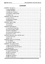
Page 3: ...rted 15 4 1 Unpacking and Inspection 15 4 2 Connect the Power Cables 16 4 3 Power on the Monitor 16 4 4 Connect with Patient Sensors 16 4 5 Check the recorder 16 CHAPTER 5 Measuring screen and Main me...

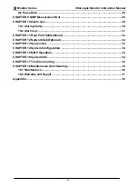
Page 4: ...iority 30 10 2 Alarm set 31 CHAPTER 11 Real Print Set Optional 32 CHAPTER 12 Network Set Optional 32 CHAPTER 13 System Set 33 CHAPTER 14 System Configuration 34 CHAPTER 15 NIBP Operation 34 CHAPTER 16...

Page 5: ...Therefore assure proper venous outflow from monitored site Sensor should be not below heart level e g sensor on hand of a patient in a bed with arm dangling to the floor Avoid placing the sensor on an...

Page 6: ...system is in correct working state and operating condition As with all medical equipment carefully route patient cabling to reduce the possibility of patient entanglement or strangulation Do not use...

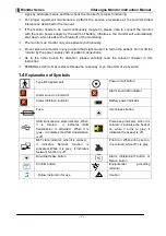
Page 7: ...ully read the relevant chapter in this instruction FEDERAL LAW U S A restricts this device to sale by or on the order of a physician 1 4 Explanation of Symbols Type BF applied part Power on off button...

Page 8: ...dult and pediatric patients in hospitals medical facilities and sub acute environments The vital signs monitor is intended for spot checking and or continuous monitoring of patients CHAPTER 2 Overview...

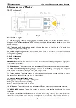
Page 9: ...Down button Press this button you can select different item and decrease the number 11 CHG indication lamp Battery charge indicator If the battery is charging the lamp will flash When the battery is c...

Page 10: ...cket is connected with the center monitor system of our company The function is reserved 3 I O for programme upgrade The function is reserved 4 Speaker 5 Power socket AC Power supply socket 6 Ground t...

Page 11: ...ughly once a month If the battery low indication icon displays during measuring please connect the monitor to AC power socket timely avoiding the current measuring is affected Warning Do not use the b...

Page 12: ...requirement Only standard 50 0 1 mm thermosensitive record paper can be used otherwise the recorder may not function the recording quality may be poor and the thermosensitive print head may be damage...

Page 13: ...lowing conditions Operating Temperature 5 to 40 Relative Humidity 80 non condensing Standard Atmosphere Pressure 86kPa 106kPa The transport and storage environment should comply with the following con...

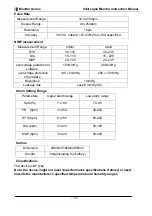
Page 14: ...g Range Parameters Upper alarm range Low alarm range SpO2 71 100 70 99 PR bpm 31 254 30 253 SYS bpm 61 255 60 220 DIA bpm 31 220 30 180 MAP bpm 31 220 30 200 Outline Dimension 296mmX166mmX96mm Weight...

Page 15: ...ing operation the instrument is free of condensation Condensation can form when equipment is moved from one building to another thus being exposed to moisture and differences in temperature 3 2 Ground...

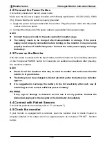
Page 16: ...After the probe is connected to its input cables turn the monitor on by momentary pressure on the front panel POWER button for 3 seconds As audible beep feedback after pressing the monitor is initiate...

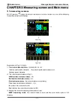
Page 17: ...008 08 25 18 00 Silence audio alarm indicator the current audio alarm status is on Battery power indicator 2 The current system status in fig 11 USB function indicator status On Net function indicator...

Page 18: ...larm limits PR alarm limits indication and measurement information The current SpO2 alarm limits Upper alarm 100 Lower alarm 95 The current PR alarm limits Upper alarm 120 Lower alarm 60 The current m...

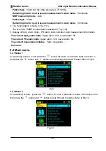
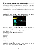
Page 19: ...ngs After entering into menu 2 press the button to select Date And Time item and press the button to confirm your selection you will see the following picture Fig 14 Press the button and button to sel...

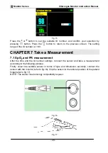
Page 20: ...99 CHAPTER 7 Take a Measurement 7 1 SpO2 and PR measurement After the time and the ID number settings connect the sensor and take a measurement according to the following pictures Firstly select the s...

Page 21: ...s Other SpO2 sensors may cause improper performance 4 Do not use a SpO2 sensor with exposed optical components 5 Excessive patient movement may cause inaccurate measurements 6 Tissue damage can be cau...

Page 22: ...f measurement available manual Auto and STAT Each mode displays the diastolic systolic and mean blood pressure WARNING You must not perform a NIBP measurement on patients with sickle cell disease or u...

Page 23: ...r company If you are not familiar with this monitor and NIBP parameters then follow this chapter sections 1 Plug in the extended tube and switch on the system Ensure the luer lock to plug into the cor...

Page 24: ...Body blood pressure is of volatility character therefore you should take several measurements in several days to judge whether or not the blood pressure is duratively increased Detailed measurement re...

Page 25: ...onged cycling of measurement serious tremble will lead to the failure of measure b Placing the cuff too loosely or tightly on the patient c Leaky cuff or hose d Insure the NIBP and pulse rate within t...

Page 26: ...us screen Fig 18 1 Fig 18 2 Select ID with 1 99 IDs selectable for data reviewing Start Print By the item you can print the records of the selected ID Stop Print By the item you can stop the print act...

Page 27: ...ID 8 3 PR Trend Review You can review the PR trend of the current ID or a different ID PR trend by setting manually In menu 1 Press the button to select the PR Trend review item and then press the bu...

Page 28: ...ation is similar to the 8 2 SpO2 Trend Review refer to section 8 2 Fig 22 1 Fig 22 2 8 6 Erase Data Select the Erase Data item in menu 2 and then press the button to enter into the Erase Data screen r...

Page 29: ...rogress will stop Manual mode under the mode press the NIBP button you can start a single measuring STAT mode the monitor will measure the blood pressure continuously in 5 minutes After completion of...

Page 30: ...alarm is activated by more than one physiological alarm each parameter will be displayed flashing with striking color meanwhile the alarm information is displayed in information column circularly AUD...

Page 31: ...he default SpO2 low alarm is 95 PR Upper alarm range 31 254 The default PR upper alarm is 120 Low alarm range 30 253 The default PR low alarm is 50 SYS Upper alarm range 61 255 The default PR low alar...

Page 32: ...a with the range of 4 40s Numbers for selection contain 4 8 12 16 20 24 28 32 36 40 Auto Print Start Print By the button the printer begins to print the records after about 3 seconds with the change o...

Page 33: ...ion is reserved currently Alarm Volume Press the or button to pick the Alarm Volume sub item and press the button to confirm Press the or the button to increase or decrease the value of alarm volume A...

Page 34: ...d configuration Restore configuration you have selected Save Current configuration Save the current settings made by the current user Factory Default initial settings made by manufacturer User Saved t...

Page 35: ...ying screen can not be refreshed 1 SpO2 module damaged 2 Hang 1 Contact with local customer service center 2 Re power on cut off the AC power and fetch out DC battery Blood pressure can not be detecte...

Page 36: ...p bottom and front surfaces lightly The following admissive liquor can be used Ammonia diluted Glutaraldehyde Sodium hypochlorite bleacher diluted Mildness suds diluted Please obey the following rules...

Page 37: ...al repair team trained by our company provide this service Fittings replacement if necessary we will replace the damaged fittings according to contract The damaged fittings should be returned to us ex...

Page 38: ...ion with result form improper repair by anyone other than our company authorized service personnel The malfunction with result from improper use 18 2 5 Special warranty period required by Customer We...

Page 39: ...e cuff for adult RNC0001A 013B 1 piece 9 3 meter metal head black cuff extended tube 1 piece The optional accessories No Accessories Quantity 1 SpO2 probe for adult Model M 50G19CSO 1 piece 2 SpO2 pro...

Page 40: ...Via Bruxelles 3 Meleto 52022 Cavriglia Arezzo Tel 39 055 96 21 11 Fax 39 055 96 21 200 www morettispa com info morettispa com...

Reviews: