background image

8

9

INSTALLATION GUIDE

INSTALLATION GUIDE

SAFETY WIRE INSTALLATION

1.Arrange and secure the safety wires as 

   above.

2.Ensure the safety wire is securely affixed 

   onto the hanging hook. Tighten safety 

   wire screw onto the pipe.

            Install safety wires correctly to 

            avoid it accidentally dropping off and causing injuries.


Pipe

Safety Wire Screw

Safety Wire

Hook

CANOPY INSTALLATION

 Secure the upper canopy by tightening the screw 

   approximately 5mm distance from the ceiling.

 Secure the lower canopy by tightening the screw 

   approximately 7mm distance from the fan motor.

5mm

About 7mm


Upper Canopy Screw ø4x8

Lower Canopy Screw 2-M3x8 

(2pcs)

(Fixing the Hole of Pipe)

ø4x8


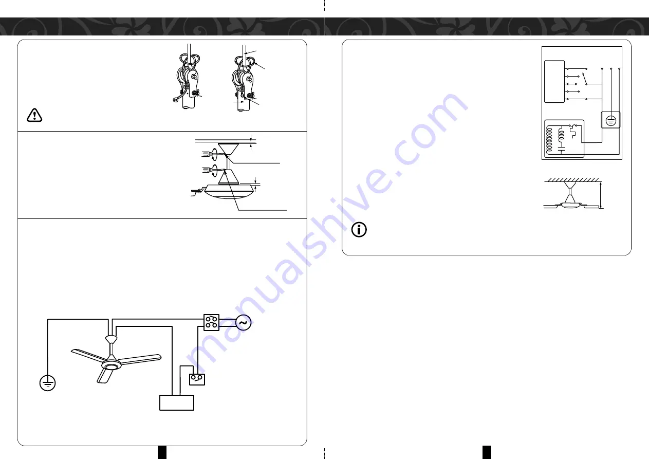
POWER SUPPLY INSTALLATION

 This appliance is not supplied with a power cord and plug.

 Engage a technician or similarly qualified person(s) to connect or replace the power cord

   or lead wire to avoid any hazards.

 Use only 2271EC53(RW) or tube thickness of 1mm or above. (Please use the country's

   wiring regulations for other requirements such as lead wire diameter).


Earth

Ceiling Fan

Regulator

Wall Switch (On/Off)

Double pole single throw switch (Switch Breaker)

220-240V~50Hz
Power Supply

N

L


REGULATOR INSTALLATION

1.Mount the regulator base onto the wall with screws.
2.Remove the regulator cover by loosening the screws. 

   Insert the live wire from the wall through the hole of the 

   base.

3.Connect the wires according to the circuit diagram above.
4.Reassemble the front cover to the base by tightening the 

   screws.

FINAL CONFIRMATION

 Measure the distance using a measuring tape.

 Ensure that all blades are of equal distance from the ceiling

   to the blade tip (within 1mm tolerance).

 Ensure that the screws, bolts and nuts are securely 

   tightened.

           Ensure ceiling fan is not wobbling after installation.
           WARNING: May cause injuries if ceiling fan falls off.


CAPACITOR

DOWN

ROD

MOTOR

THERMAL FUSE

ROTARY
SWITCH

1

2

3

4

5

CIRCUIT DIAGRAM

L

E

N

Check Height

C


Summary of Contents for MFC-Eurus 360BK

Page 1: ...ANUAL MFC Eurus 360BK MFC Eurus 360WH MFC Eurus 360BW MFC Eurus 360GR E mail electrical appliance dksh com www morgan my Market Expansion Services by www dksh com my facebook com morganappliances Ceiling Fan ...

Page 2: ... electrical shock or injury to persons or property please read and follow below instructions carefully The ceiling fan must be hooked on concrete ceiling Do not install on a plaster ceiling or any type of drywall ceilings During installation all screws must be tightened at all indicated parts Always operate the product from a power source of the same voltage frequency and rating as indicated on th...

Page 3: ...ance when relocating it The ceiling fan must be mounted above 2 5m from the floor and at least 1m from the wall to the fan blade To avoid injuries caused to users or any damage to properties please follow all the symbols with explanations written below WARNING CAUTION 1 2 3 4 5 6 9 10 11 12 15 8 7 14 13 1 Pulley 2 Bolt 3 Upper Canopy 4 Canopy Screw 5 Pipe 6 Bolt 7 Cotter Pin 8 Nut 9 Terminal 10 Lo...

Page 4: ...e Green to terminal 3 Second connect NEUTRAL wire Blue to terminal 2 Lastly connect LIVE wire Brown to terminal 1 Ensure all terminals are connected correctly by suitably qualified persons to avoid the risk of electric shocks and other hazards 6 Secure the cord as shown in the illustration using the insulock tie Do not secure the safety wire with the insulock tie Loose insulock tie and cords touch...

Page 5: ... to avoid any hazards Use only 2271EC53 RW or tube thickness of 1mm or above Please use the country s wiring regulations for other requirements such as lead wire diameter Earth Ceiling Fan Regulator Wall Switch On Off Double pole single throw switch Switch Breaker 220 240V 50Hz Power Supply N L REGULATOR INSTALLATION 1 Mount the regulator base onto the wall with screws 2 Remove the regulator cover...

Page 6: ...ations repairs electrical or mechanical adjustments Keep the fan clean regularly by wiping dirt away with a clean soft cloth mild soap and water Ensure it is dry by wiping again Do not use solvents gasoline or petrol or any abrasive cleansers to avoid damaging the exterior finishing Do not paint the fan blades If damaged order a new set of blades 3 pieces from your nearest authorized dealer or aft...

Reviews: