


23
www.morganadvancedmaterials.com
Insert Registered Legal Entity name, address and number, or all other details as required to comply with regional regulations
23
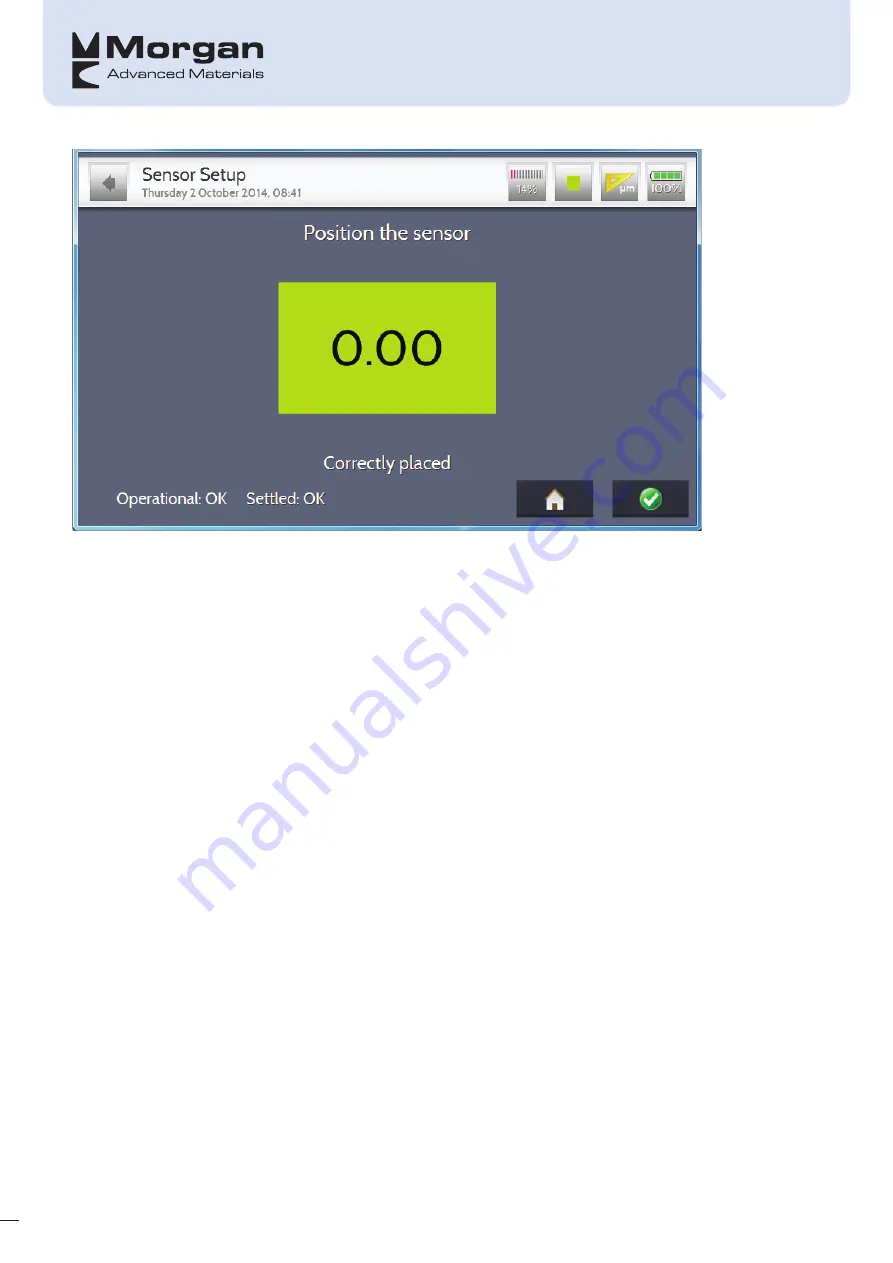
•
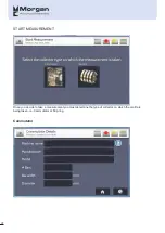
When the sensor head is in position (ideally the display will be green), tighten the clamp in the holder or
sleeve fully so that there is no movement from the sensor. Only hand tighten the sensor and do not use
any tools or other equipment (as over tightening may damage the clamp).
•
Mark the collector surface so that a reference start/stop point can be located
•
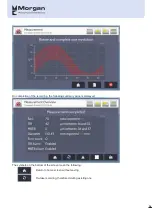
Next, the collector needs to be rotated in the direction in which the profile will be taken in order to stabilise
the sensor; if a full rotation is not possible then the collector must be rocked back and forth slightly
–
note
that for consistent results the last movement must be in the same direction as that in which the profile will
be taken. Note that the ‘Operational’ and ‘Settled’ flags (on bottom left hand side of the screen) will
change to ‘OK’ once this has been carried out correctly.
•
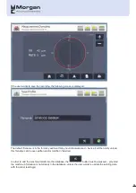
Check the display still reads ±0.2mm (±8mil) or less and if you are measuring a commutator also ensure
that the sensor is still located approximately in the middle of the marked bar
•
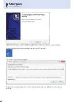
It is possible to continue when the sensor has not been placed correctly, i.e.
when the arrow is orange
however an additional warning appears advising you of the issue.


