background image

Operator Manual 

DigiBook 150 

75 

Rev. 1.00-C 

16


Problems - Solutions 

16.1


CHIPS ASPIRATOR – LESS VACUUM: 

Verify that the Plexiglas inspection, located on the Milling Station, is free.

Verify that the chips aspirator tank is empty.

Verify that the chips aspirator tube is not full of chips.

Verify that the aspirator filter is clean.

Check that the hose is connected.

16.2


CLAMP – IT DOESN’T START: 

Verify the presence of a book.

Verify that the emergency switch is disabled.

Verify that the book detecting photocell and the related reflector are clean.

Verify that the photocell or the reflector of the press is free from books, pieces of paper or durst.

Verify that the clamp jaws are free from glue residues.

Verify the air pressure in the machine.

Verify that the carriage has made the zero placement the display is located on the main page?

Verify that you are on the main page

16.3


MILLING STATION – IRREGULAR CUT AND NOTCHING: 

Verify that the Milling disk is not broken or damaged. This could happen by the management
of  books  already  bounded  with  glue  (TO  AVOID). 

IF  IT  IS  NOTICED  THAT  GLUE

BOUNDED BOOKS HAVE BEEN MILLED: THE GUARANTEE VOIDS

16.4


COVER PLATE MILLING STATION – IT DOESN’T OPEN / CLOSE CORRECTLY: 

Clean carefully the contact surfaces if the milling station box.

16.5


HEAD - OUT OF TOO MUCH OR LITTLE GLUE: 

Verify the air pressure of the glue group.

Verify that the head shutter is free, using the provided blade.

Verify that the side


holes are free, using the provided steel wire.

Verify that the injectors are working properly (they must move back and forth 3-4 mm).

Verify the glue presence in the tank.

Verify that the glue in the tank is not hard-glue.

Verify that the tank valve is open.

Verify the position of the internal lateral jaw: it must be 0.15 tenths back from the edge of the
clamp.

16.6


NIPPING STATION 

Dent book, clean the surfaces with proper solvents without using abrasive products.

Edge pinched: contact technical support.

MyBinding.com

5500 NE Moore Court 

Hillsboro, OR 97124 

Toll Free: 1-800-944-4573 

Local: 503-640-5920

Summary of Contents for DigiBook 150r1

Page 1: ...Rev 1 00 C K G S srl DigiBook 150r1 Operators Manual MyBinding com 5500 NE Moore Court Hillsboro OR 97124 Toll Free 1 800 944 4573 Local 503 640 5920 ...

Page 2: ...__________ 14 2 TECHNICAL SHEET FOR MASTERBOOK 150 ____________________________ 15 2 1 1 Electrical ______________________________________________________________________ 16 2 1 2 Pneumatics_____________________________________________________________________ 16 Air quality provided to the Master Book _____________________________________________________ 17 DIN ISO 8573 1 air quality class _______...

Page 3: ...OOK _____________ 57 13 1 STARTING THE MACHINE __________________________________________________________ 58 14 BOOK SPINE PREPERATION ____________________________________________ 61 14 1 PREPERATION OF LARGER BOOKS________________________________________________________ 62 14 2 CHANGING THE NOTCHING TOOL HEIGHT __________________________________________________ 63 15 CLEANING THE MACHINE ________...

Page 4: ...on and a wide range of functions This manual describes how to use the machine starting from the configuration phase to the most important operations This manual has been written in order to be easily understood also by user not trained about the use of this kind of machine For the best use of the equipment please read careful ly this manual before to use the machine After reading we suggest you to...

Page 5: ...TURE OF MODELLO TIPO MODEL TYPE PERFECTBINDER MASTERBOOK 150 MATRICOLA SERIAL MB150 XXXX ANNO DI COSTRUZIONE MANUFACTURED IN 2013 CORRISPONDE ALLE SEGUENTI DISPOSIZIONI NELLA VERSIONE ATTUALMENTE VALIDA IS IN AC CORDANCE WITH THE FOLLOWING DIRECTIVES AS IT IS Direttiva CE per Macchine 2006 42 CE Directive 2006 42 CE Direttiva EMC 2004 108 CE EMC Directive 2004 108 CE Direttiva sulla Bassa tensione...

Page 6: ...treme situations also fatal accidents Together with the symbols it is written also what to do Attention General danger Attention Electrical voltage Risk of electric shock Attention Sharp blades Risk of cut Attention Hot surfaces Risk of burn Attention Risk of rolling parts Risk of crushing Attention Risk of moving chain Risk of crushing In case of not warning of the symbols damages also great can ...

Page 7: ...bition This symbol means an imperative This symbol means that it is mandatory to read in this manual information re garding specific topics for ex related to the specifications of the electric and pneumatic connection MyBinding com 5500 NE Moore Court Hillsboro OR 97124 Toll Free 1 800 944 4573 Local 503 640 5920 ...

Page 8: ... safety rules It is forbidden to use the machine when occurs one of the following situations in explosive environment in flammable atmosphere in excessive dusty environments Danger Failure to comply with some or all the instructions listed in this manual could cause damage to the machine and or personal injury The manufacturer is not re sponsible for an arbitrary and improper use of the machine su...

Page 9: ...g a protective screen Do not wear watches or jewelry Safety clothing The safety clothing IS NOT INCLUDED in the machine and must be pro cured by the machine user The operator should wear clothing appropriate to the situation and special ly during the following operations Maintenance Replacing of the PUR glue Cleaning of the PUR system a Eye protection against any spray of PUR glue or high temperat...

Page 10: ...larm signals due to the intervention of the safe ty the operator must request the immediate intervention of technical people trained on the maintenance The manufacturer is not responsible of any damage to persons or animals caused by tampering with the guards 1 7 1 EMERGENCY BUTTON It is located on the front easily accessible from the operator s position In the diagrams the emergency button is ide...

Page 11: ... all this happens if I put the book block in the clamp and place a cover on the press 1 7 3 PROTECTION PLATE OF THE MILLING STATION The plate consists of a mobile plate that except when the book block is moving covers the cutter in all operating conditions even at a standstill A spring exerts a constant force on the plate a force that covers the mill disc The motor of the cutter is equipped with a...

Page 12: ...N SWITCH It is located on the right side of the machine Position OFF The switch is open The machine is off Position ON The switch is closed The machine is on MyBinding com 5500 NE Moore Court Hillsboro OR 97124 Toll Free 1 800 944 4573 Local 503 640 5920 ...

Page 13: ...ead Attention Hot surfaces Risk of burn Use protective gloves Area of glue loading Attention Hot surfaces Risk of burn Use protective gloves Area of the mill The disc contains several types of milling cutters Use protec tive gloves in case of remov ing the Notching Roughening or the brush MyBinding com 5500 NE Moore Court Hillsboro OR 97124 Toll Free 1 800 944 4573 Local 503 640 5920 ...

Page 14: ...D USES PROHIBITED USES Any other use such as Milling Roughening of book spines already bounded adhesive binder stitching book sewing book etc Use of materials other than those specified in a and b Operations beyond the technical specifications are not to be re garded as intended use The user has the total responsibility of the damages to people or things due to an improper use outside of their int...

Page 15: ...p Manual Clamp opening closing Manual Spine preparation Milling disks Ø 110 mm optional Roughening for spine processing 2 Chips aspirator Included in the machine Glue application system Tank PUR Hot Melt glue 3 Kg sealed Extrusion system of PUR Hot melt integrated and sealed Extrusion head adjustment Manual Glue stops Adjustable by Touch Screen Cleaning sealing Yes Press Press Electric servo contr...

Page 16: ...aracteristics for the machine Compressed air consumption 100 Nl min Calibration of input gauge 6 bar Min working pressure 5 5 bar If the pressure value falls below this value the machine enter in an alarm condition Diameter of air inlet 6 mm The 6 mm diameter house for the connection to the compressor is not provided together with the machine It is suggested the use of a compressor equipped with t...

Page 17: ...matic device must have the following quality features Pressure Quantity Water content Solids content Oil content DIN ISO 8573 1 AIR QUALITY CLASS The manufacturers of pneumatic components refer to the quality of compressed air to be used on their products referring to the table below The compressed air used in the industry contains water oil dust and other impurities The interac tion of these elem...

Page 18: ...leakage of the lateral glue Lamella thickness of 0 4 for cleaning the slit of leakage of the spine glue Spare Headless screws for the closure of the ducts Protective gloves Set of allen keys Small arches for supporting the book block in the clamp START UP KIT One pack of 2 kg of PUR Glue Henkel One pack of 2 litres of beans Cleaner Blue Henkel MyBinding com 5500 NE Moore Court Hillsboro OR 97124 T...

Page 19: ...afety protections suit shoes gloves hel met and glasses Attention The machine is balanced In any case keep the forks low In case of unbalance use weights It is forbidden to hold by the hands the project ing parts The machine and its parts must be protected from the weather outside In particular water dust and moisture can oxidize certain elements of the machine damaging them irreversibly Follow th...

Page 20: ... carrying in SAFETY Horizontal bolster Horizontal bolster must have a capacity in excess of the total mass of the machine In the case of removal or unused for long peri ods over 30 days it is necessary to drain the glue system and to put inside the protection cleaner The damage caused by this failure will void the warranty of the glue device During periods of downtime you should not open the tank ...

Page 21: ...Operator Manual DigiBook 150 21 Rev 1 00 C 6 LAYOUT ...

Page 22: ... Workspaces Glue loading area Glue loading area the operator enter in this area to load the glue in the machine Access area for the maintenance for access to the electrical and pneumatic panel Transit area Used to transit from the work area to the glue loading area Operator s work area Operator s work area during the normal use of the machine Right side of the machine It is not necessary to leave ...

Page 23: ... For the installation you must choose an operational area depending on the size of the machine parts and lifting equipment selected and pay attention to the presence of any obstacles on the road equipments walls etc 8 3 BOLSTER The machine requires no special foundations It must be ensured the availability of an industrial floor The producer has no responsibility about construction of foundations ...

Page 24: ...he table below In case of use of the system in corrosive environments it is important to intervene in the mainte nance of the machine with adequate time to avoid excessive wear of components MIN MAX Room temperature 5 C 40 C Relative humidity 20 80 MyBinding com 5500 NE Moore Court Hillsboro OR 97124 Toll Free 1 800 944 4573 Local 503 640 5920 ...

Page 25: ...gth of 3 meters with sectioned end with the earth conductor PE It is the responsibility of the user to adjust the connection cable in accordance with the appli cable legislation 8 7 1 GROUND CONNECTION The Perfect Binder is equipped with an earth conductor PE During the installation the customer must realize the ground connec tion in accordance with the applicable legislation MyBinding com 5500 NE...

Page 26: ...avoiding taking personal initiatives It is assumed that the operating and maintenance personnel possess the following minimum re quirements Culture in general and specific enough each to his ability to read and understand the con tents of the manual including the correct interpretation of drawings and diagrams pneumatic and hydraulic Ability to understand correctly the symbols and video messages O...

Page 27: ...book and the glue stop select the correct speed base of book thickness 8 Open the clamp at the thickness of the book you want to produce 9 Open the head at the thickness of the book you want to produce 10 Position the cover on the rear ledge of the press at the desired dimension 11 Put the book in the clamp a put the cover b close the clamp c press together the two buttons placed on the front part...

Page 28: ...t 600g of Blue Cleaner and make it pro trude from the main slot and the channel of the glue if at the end of this cleaning cycle you are not sure that from the valve 100 Blue Cleaner exits repeat the operation Never open the tank when it is cold Possibility to break the seal gasket In addition to that the air humidity will en ter into the tank and will be trapped causing premature ageing of the gl...

Page 29: ...n glue nozzle use the temperatures suggested by glue producer Avoid opening the lid frequently the moisture in the air damages the features and durability of the glue The depletion of the glue is found in two ways the lack of glue on the book issuing at the extrusion zone glue clear glue mixed with air vents and glue bubbles When you finish the glue and in sert a new cartridge you have to wait abo...

Page 30: ...to the quick of the Master Book To disconnect the hose of the machine it is necessary to rotate the blue part of the sleeve With this proce dure you will flush the air from the machine When you have finished it will be possible to pull out the sleeve pushing upwards the blue part and pulling out the sleeve downwards The sleeve has a seal system that once pulled out does not allow air passage Dange...

Page 31: ...losed The machine is on 1 CLAMP 2 MILLING STATION 3 GLUE STATION 4 PRESS 1 CLAMP A Tag for book thickness B Knob to adjust the slot C Lever for opening closing D Sensor for presence of book E Front support for the book F Rear support for the book MyBinding com 5500 NE Moore Court Hillsboro OR 97124 Toll Free 1 800 944 4573 Local 503 640 5920 ...

Page 32: ... NO GLUE do not use the machine Pressure from 1 2 to 1 8 bar for books un til 5 mm thickness Pressure from 1 8 to 2 bar for books from 5 to 10 mm thickness Pressure from 2 to 3 bar for books from 10 to 30 mm thickness Pressure more than 3 bar for books from 30 to 50 mm thickness C Adjustment for head slot Values of slot min 1mm Max 50mm D Bowl for glue collection MyBinding com 5500 NE Moore Court ...

Page 33: ...d over the machine I Access to glue tank II Access to cleaner tank The machine does movements only when the panels are closed 3 A GLUE TANK 3 B CLEANER TANK A Handwheel to open the tank B Valve ON OFF for air in tank C Handgrip to open D Valve to drain glue MyBinding com 5500 NE Moore Court Hillsboro OR 97124 Toll Free 1 800 944 4573 Local 503 640 5920 ...

Page 34: ...tube and electrically connected he switches on and off together with the Milling Station Front picture chips aspirator see arrow Aspiration tube In the back of the Perfect Binder connected to the back preparation station Switch It must be in on position I ON during the operation of the Perfect Binder Every day the chips aspirator must be emptied and cleaned to be always effi cient MyBinding com 55...

Page 35: ...ARNINGS ON THE OPENING OF PUR TANK Wear hand protection all parts are at high temperatures Wear protections for face respiratory mask suitable for the glue you are using and protection glasses Never open the tank when it is COLD Possibility of breaking the seal gaskets and because of this The air moisture would enter and remain trapped in the tank causing premature aging curing of the PUR glue wit...

Page 36: ...ay the pressure to the glue tank while the cleaner tank remains under pressure of 2 bar about Loosen the lock knob Turn it counter clockwise Attention High temperature Wear protective gloves Tilt locking knob to its rest position The cover is so free to open Lift the cap to the maximum opening grabbing the lateral knob MyBinding com 5500 NE Moore Court Hillsboro OR 97124 Toll Free 1 800 944 4573 L...

Page 37: ...xpiration date printed in the package Please read the SAFETY cards of the used glue and follow all the instructions of the manufacturer Cut the foil by using a sharp tool Remove completely the foil Insert the cartridge into the tank Attention High temperature Use protective gloves MyBinding com 5500 NE Moore Court Hillsboro OR 97124 Toll Free 1 800 944 4573 Local 503 640 5920 ...

Page 38: ...paying attention to high temperature components Turn the knob clockwise vigorous ly to tighten the tank Close the sliding panel in the back of the machine provided with a handle MyBinding com 5500 NE Moore Court Hillsboro OR 97124 Toll Free 1 800 944 4573 Local 503 640 5920 ...

Page 39: ...structions of the manufacturer By loosening the knob of the cleaner tank you will notice an air leak this is normal as the machine continues to pro vide air to the tank Fill the tank with cleaner to about 3 4 of its volume by using a small container Close the cap using the knob on the side and pay attention to the high temperature com ponents Lift the locking knob MyBinding com 5500 NE Moore Court...

Page 40: ...1 00 C Tighten the knob until the noise of escaping air disap pears Close the sliding door in the back of the machine provid ed with a handle MyBinding com 5500 NE Moore Court Hillsboro OR 97124 Toll Free 1 800 944 4573 Local 503 640 5920 ...

Page 41: ...nary Operations Turn on the machine using the main switch While you are doing this on display you will see the set up page from which it will be possible to access to the main features of the Master Book see image below MyBinding com 5500 NE Moore Court Hillsboro OR 97124 Toll Free 1 800 944 4573 Local 503 640 5920 ...

Page 42: ... do the pre set of the machine 5 The press automatically comes up 6 Open the clamp as indicated by the display If the clamp does not open the machine does not allow the carriage to go back Due to the sensitiveness of the sensor it can happen that with big thickness books 50 mm the sensor keeps reading that the clamp is not opening In this case after open it press the button OK in order to allow th...

Page 43: ...button for cleaner cycle or glue cycle 8 Icon button to access to alarms window if the icon has a red background you have alarms or warnings on 9 Icon button set the speed of the machine depending on the thickness of the book 10 Icon button to set up nipping time 11 Icon button for book counter ex 0 on right side of the icon highlighted with 1 on the drawing shows you the produced copies left side...

Page 44: ...able indicate the current temperature of the glue pot and the nozzle If the thermometer is red the gluing station is no ready if green it is ready to glue 15 Status indicator for sensors date and time 16 Red icons not activated indicate an eventual off status for the milling and nipping station Buttons functioning Following the previous buttons numbering let s see their functions 1 In order to do ...

Page 45: ...he direction below the selection made a green checkmark will appear and press to gether the two buttons on the front part of the machine until the desired position The num ber below the clamp indicates the current position for the carriage 3 Icon milling station button Once the icon is pressed the window below will appear Here you can decide if you want to run the milling station or not during the...

Page 46: ... timer set up on 1800 Sec Pressing on the hand you access to windows for manual movements for the nozzle see be low The temperatures must be set up according to the kind of glue you are going to use please refer to the temperatures suggested by the glue producer The premelter temperature must be 5 to 15 C lower compared to that one of the extruder During the heating phase the indicators will be re...

Page 47: ...the glue valve Keeping pressed the button less than 2 sec but more than 1 sec you open and auto matically close the glue valve filling and putting under pressure the glue tank This pressure is maintained for 10 sec Holding the button more than 2 sec you open and automatically close the glue valve putting under pressure the glue tank and the glue comes out from the nozzle until you hold the button ...

Page 48: ...htness for the display access to technical service area using a password 7 Icon cleaner and glue cycle button When the icon is pressed more than 1 sec the window below will appear Follow the instructions on display to execute the cycle pressing the blue or white arrows icons you make the fluid to go out if that one that has been set up is not enough To go out without finishing press whichever icon...

Page 49: ...has not achieved the position in the specified time Check it s movement A07 Error relay heating Reset the alarm if the problem persists contact technical support A08 Error milling station supply Check the fuse FU13 01 A09 Cleaner present At shutdown of the machine the head cleaning has been made with the automatic cycle of the cleaner Use the loading glue cycle load the glue The machine with this ...

Page 50: ...d of counter to be visualized on the main window Press the corre spondent icon Total counter not resettable Partial counter resettable with a dedicated button Daily counter resettable with a dedicated button When you have selected the kind of counter to be visualized on the main window the icon too changes in order to indicate it 12 Icon kind and dimension for the book button When the icon is pres...

Page 51: ...d it is not possible to make glue and cleaner cycle 15 Indicators for sensors first box is green if the carriage preset sensor is on second box is green if the closed clamp sensor is on when you have the carriage in the initial position third box is green if the closed clamp sensor is on when the carriage is on the nip ping station fourth box is green if the nipping station is down fifth box is gr...

Page 52: ...Operator Manual DigiBook 150 52 Rev 1 00 C 17 Previously described MyBinding com 5500 NE Moore Court Hillsboro OR 97124 Toll Free 1 800 944 4573 Local 503 640 5920 ...

Page 53: ... case the machine has been switched off with the END OF JOB procedure it will be possible to start working only doing a glue refurbishment An error message appears Machine with Cleaner Primary condition machine in temperature tank valve open in vertical position Hold the button for few seconds to start the GLUE REFURBISHMENT procedure Follow step by step the instructions on display Adjust the mano...

Page 54: ... Blue cleaner disappears Help the glue to exit from the bin by using the green spatula Help themselves with the fin calibrated in this operation Clean carefully all the excess spillage using the spatula and paper towels Replace the headless screws using the L wrench provided beware of temperature press OK Attention Headless screws max protrude 1 mm Now the machine is ready to work ...

Page 55: ...ster B The value A indicated in dicates is the same as the X dimension Position the cover manually as shown by the arrows against the eccentrics indi cated on the side and against the cover register B see previous picture MyBinding com 5500 NE Moore Court Hillsboro OR 97124 Toll Free 1 800 944 4573 Local 503 640 5920 ...

Page 56: ... standard calibration requires that the angle be tween the sides of the cover is 90 If the cover has some problems caused by im proper trimming you can adjust the placement by adjusting the position of the eccentric on the opera tor side MyBinding com 5500 NE Moore Court Hillsboro OR 97124 Toll Free 1 800 944 4573 Local 503 640 5920 ...

Page 57: ...nected to the Master Book and its power switch is in position 1 ON Check that in the tank there is a minimal amount of glue to allow manufacturing several books otherwise insert a new cartridge of glue inside the tank Glue collection tank flushed Ensure that the Master Book is clean and without books or covers especially Clamp Silent Plate Milling Station PUR head Press Check that the temperature ...

Page 58: ... 03 Open the valve on the premelter The valve with the lever in vertical position means that is open 04 Verify the selected temperatures 05 Wait for heating phase 06 Press the key Do the glue recovering procedure At the end of the glue recovering process the machine performs a series of closing opening cycles of the glue valve 07 Digit the parameters for front back and book length glue stops 08 Se...

Page 59: ...le at the end of the press 12 Adjust the thickness of the book loosing the knob B then move the front jaw until the measure of the book thick ness you read on tag A Turn the knob B 13 Load the fascicle in the clamp as indicated from the ar rows in the image 14 Close the clamp as indicated MyBinding com 5500 NE Moore Court Hillsboro OR 97124 Toll Free 1 800 944 4573 Local 503 640 5920 ...

Page 60: ...tation when it will reach the position the press will put the cover 17 Open the clamp 17 Press together the two keys on the front side of the ma chine 17 The clamp will return to the loading position Take away the book from the press and repeat all the points from 11 if you want to produce a book with the same characteris tics MyBinding com 5500 NE Moore Court Hillsboro OR 97124 Toll Free 1 800 94...

Page 61: ...loves is recommended during this procedure Use a 5mm L Wrench turn turn the milling disc clockwise into the required position Remove the notching tool screw Insert the supplied M6 x 30 screw into the vacant hole and then extract the notching tool Turn the tool 180 degrees and replace so that the cutting side is inside the milling head This operation balances the cutter for better spine preperation...

Page 62: ...Operator Manual DigiBook 150 62 Rev 1 00 C Reverse the procedure when using books smaller than 31mm MyBinding com 5500 NE Moore Court Hillsboro OR 97124 Toll Free 1 800 944 4573 Local 503 640 5920 ...

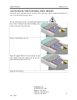
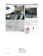
Page 63: ... protective gloves is recommended during this procedure Use a 5mm L Wrench turn turn the milling disc clockwise into the required position Remove the notching tool screw Insert the supplied M6 x 30 screw into the vacant hole and then extract the notching tool Remove the spacer underneath and refit the tool Repeat for the 2nd tool MyBinding com 5500 NE Moore Court Hillsboro OR 97124 Toll Free 1 800...

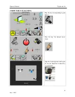
Page 64: ...of job cleaning it is possible to save the machine turned off containing PUR glue for 2 weeks COMPULSORY CLEANING for proper operation of the machine If the machine is switched off or unused for more than 120 minutes it is necessary to make the cycle of End of job cleaning EVERY DAY END OF JOB CLEANING EMPTY THE CHIPS ASPIRATOR ONCE IN THE WHEEK CLEANING SIDE EXTRUDER CLEANING SPINE EXTRUDER CLEAN...

Page 65: ...roce dure During this phase the glue group prepares for daily cleaning Follow step by step the instruction on display Use the green spatula included and make the glue flow in the collection tank Try to remove as much as possible of the re leased glue Press until all the glue traces disappear For this operation help yourself with the calibrated blade Press until from the extruder exits only cleaner...

Page 66: ...66 Rev 1 00 C 15 2PROCEDURE TO CLEAN THE SPINE GLUE EXTRUDER Press the key that corresponds to the glue station Press the key for manual movements Open the glue head until dimension 52 Use the small wheel indicated with A see below ...

Page 67: ... the bottom and move it along the slot to re move or release any possible ob structions Adjust the value of the glue ex trusion pressure to 1bar using the regulator A This value can be read on the manometer B MyBinding com 5500 NE Moore Court Hillsboro OR 97124 Toll Free 1 800 944 4573 Local 503 640 5920 ...

Page 68: ... the glue extrusion is uniform and continous other wise insert the calibrated blade and repeat the cleaning operation The tank pressure will turn off af ter 10 sec of inactivity Thoroughly clean the blade When the glue is fully cured the blade will no longer operate MyBinding com 5500 NE Moore Court Hillsboro OR 97124 Toll Free 1 800 944 4573 Local 503 640 5920 ...

Page 69: ...E SIDE EXTRUDERS Press the key corresponding to glue station Press the key for manual movements Open the buttering head until quote 52 Use the Handwheel indicated by A see below MyBinding com 5500 NE Moore Court Hillsboro OR 97124 Toll Free 1 800 944 4573 Local 503 640 5920 ...

Page 70: ...usion of the side glue you must remove the headless screw and insert in the holes the in cluded wire Repeat this operation on the two plates of containment of the book To get a correct extrusion of the side glue you must remove the headless screw and insert in the holes the in cluded wire MyBinding com 5500 NE Moore Court Hillsboro OR 97124 Toll Free 1 800 944 4573 Local 503 640 5920 ...

Page 71: ... enter into the below slot Be careful When you replace the headless screws they cannot pro trude otherwise you cause a collision with the nipping station Attention Headless screws max pro trude 1 mm MyBinding com 5500 NE Moore Court Hillsboro OR 97124 Toll Free 1 800 944 4573 Local 503 640 5920 ...

Page 72: ...ual DigiBook 150 72 Rev 1 00 C 15 4DETAILS CLEANING Press the key corresponding to glue station Press the key for manual move ments Open the buttering head until quote 52 Use the Handwheel indicated by A see below ...

Page 73: ... the included blade to re move all the visible glue trac es If necessary you can use liq uid solvents to get a better cleaning of the surface During the use of liquid sol vents refer to the safety in structions provided by the solvent manufacturer ...

Page 74: ... that do not leave any remain Use scraping off tools that do not damage the internal surface of the premelter Avoid that parts of cured glue remain inside the premelter These would occlude the nozzle If the premelter is too dirty or crusted please call the assis tance to wash it with proper solvents MyBinding com 5500 NE Moore Court Hillsboro OR 97124 Toll Free 1 800 944 4573 Local 503 640 5920 ...

Page 75: ...ING Verify that the Milling disk is not broken or damaged This could happen by the management of books already bounded with glue TO AVOID IF IT IS NOTICED THAT GLUE BOUNDED BOOKS HAVE BEEN MILLED THE GUARANTEE VOIDS 16 4 COVER PLATE MILLING STATION IT DOESN T OPEN CLOSE CORRECTLY Clean carefully the contact surfaces if the milling station box 16 5 HEAD OUT OF TOO MUCH OR LITTLE GLUE Verify the air...

Reviews: