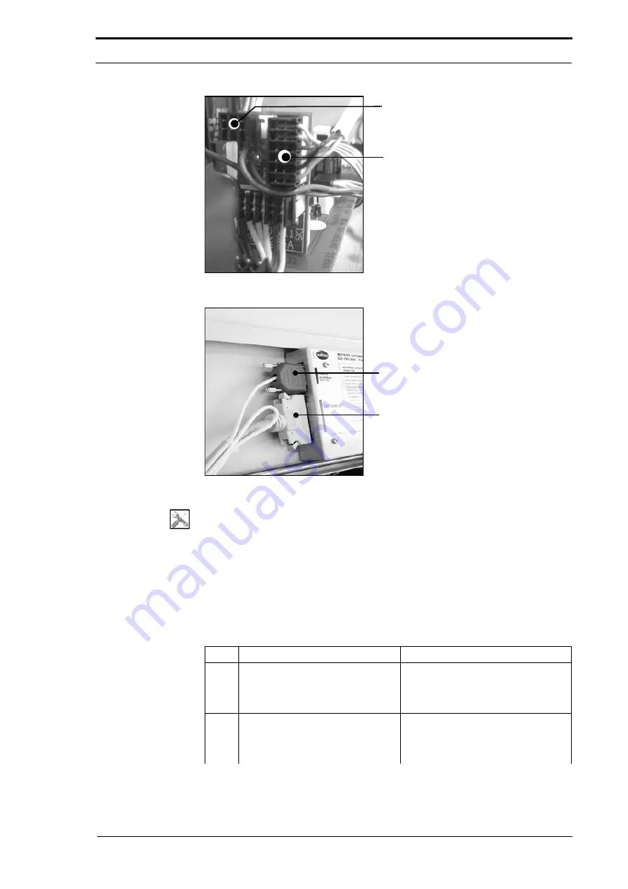
PL3 - Feed Signal Cable
PL2 - PWM Signal Cable
4. Service Procedures - Replace Components - DRV Module
108
Morgana DocuMaster MFC - Service Manual
Figure 4.89
Signal Interface PCB Connections
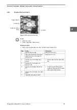
RS232 Serial Comms Connector
GUI Panel Interface Cable
Figure 4.90
CPU Serial Comms and GUI Connections
Tools:
•
Allen Key: 3mm
•
Spanner: 10mm, 14mm
•
Pliers: Side Cutters.
Before you start:
•
Remove the RH and LH side covers (See Section 4.2.5) and (See Section 4.2.6)
•
Remove the rear guard (See Section 4.2.7)
•
Remove the CAP (See Section 4.6.1).
Step
Action
Information
1
Disconnect the Power Bus and
Data bus cables from the interface
PCB. Pull the cables out through
the RH side plate.
2
Disconnect the feed-signal cable
from PL3 on the signal interface
PCB. Pull the cable out through the
RH side plate.
Summary of Contents for DocuMaster MFC
Page 8: ...CONTENTS vi Morgana DocuMaster MFC Service Manual ...
Page 9: ...Morgana DocuMaster MFC Service Manual 1 1 SECTION 1 Introduction ...
Page 27: ...Morgana DocuMaster MFC Service Manual 19 2 SECTION 2 Error Conditions ...
Page 43: ...Morgana DocuMaster MFC Service Manual 35 3 SECTION 3 Output Quality Problems ...
Page 46: ...3 Output Quality Problems Crease Quality 38 Morgana DocuMaster MFC Service Manual ...
Page 47: ...Morgana DocuMaster MFC Service Manual 39 4 SECTION 4 Service Procedures ...
Page 196: ...4 Service Procedures The MFC Maintenance Schedule 188 Morgana DocuMaster MFC Service Manual ...
Page 197: ...Morgana DocuMaster MFC Service Manual 189 5 SECTION 5 Parts Lists ...
Page 199: ...Morgana DocuMaster MFC Service Manual 191 6 SECTION 6 General Procedures ...
Page 221: ...Morgana DocuMaster MFC Service Manual 213 7 SECTION 7 Electrical and Control System ...
Page 259: ...Morgana DocuMaster MFC Service Manual 251 8 SECTION 8 Installation Manual ...
Page 266: ...8 Installation Manual Install the MFC 258 Morgana DocuMaster MFC Service Manual ...
Page 267: ......


