Page 44
Replacing Blade Set
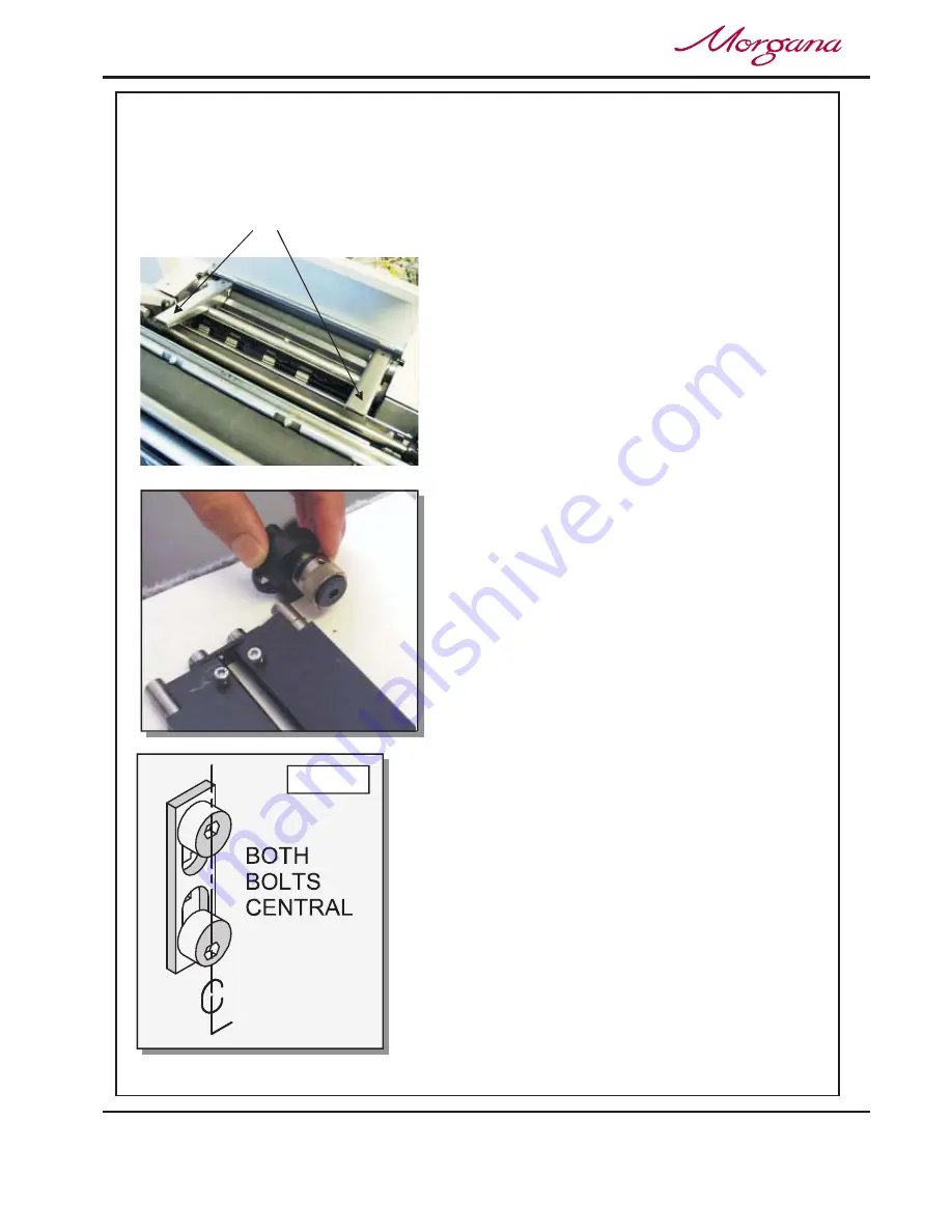
Blade Extractor Tools
FIG 20.1
CREASING / BOOKLET MAKING
1. Before removing the blade assembly, ensure that the lower blade / anvil is NOT
at ‘top dead centre’, Switch the machine off.
2. Remove the stacker unit and lift the exit guard.
3. Using a 6mm allen key, loosen the socket
head screws located inside the blade
adjustment cams. Remove the screws and
the blade adjustment cams.
4. Insert the blade extractor tools (70-055-01 &
70-055-02) into the holes in the adjustment
links, as shown. Push downwards on the
handles of the blade extractor tools to
release the blade assembly from the power
links.
5. Slide the blade assembly out of the creasing
unit and lay it on a flat surface.
6. Slide the adjustment links away from the
dowels located in the ends of the blades /
anvils as shown in the photograph (left)
7. Place the new blade set into position.
Check that the eccentric shoulder bolts on
the link plates have been positioned as
shown in fig 20.1.
8. (Upper blade / anvil only)
Slide the adjustment links onto the dowels.
9. Slide the new blade set into the slots of the
creasing unit as shown in fig. 21.1.
Locate the blade extractor tools into the holes in
the adjustment links as shown. Pull the handles
of the blade extractor tools upwards to engage
the blade assembly back into the power links.
10. Set the cam graphics for both ends of the blade /
anvil to their lowest point on the scale (ie. When
the mark on the scale reaches the mark on cam
holder) Fasten the socket head screws on the
adjustment cams until they are tight.


