Page 37
SYSTEM
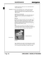
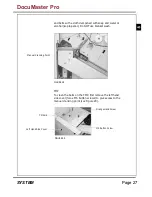
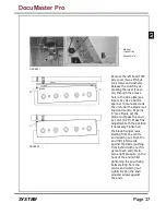
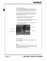
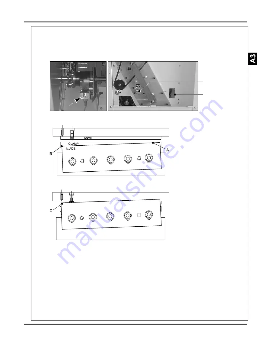
FIGURE 41
Manual
Crank Drive
Access Hole
FIGURE 42
Remove the left hand TMP
side cover (two x M5 but-
ton screws and washers).
Release the clutch by de-
pressing the lever (see ar-
ow) through the access
hole in the side plate (see
Figure 41). Use a 19mm
spanner to manually crank
the unit until the blade is at
top dead centre. At point
'C' (see Figure 42) the
blade must pass the anvil
by 1mm (1/25"). Make fine
adjustments to the position
if necessary. Tighten all
the blade fixing screws
starting from the centre
and working out. Push the
anvil firmly forwards
against the blade (pushing
from behind with your fin-
gers at each end). Main-
tain a light pressure on the
back of the anvil whilst
tightening the anvil fixing
bolts starting from the
centre and working out.
Lightly tension the anvil
adjuster screws against
the anvil.
DocuMaster Pro
Summary of Contents for Documaster Pro
Page 11: ...Page 9 SYSTEM THIS PAGE IS INTENTIONALLY BLANK DocuMaster Pro ...
Page 15: ...Page 13 SYSTEM THIS PAGE IS INTENTIONALLY BLANK DocuMaster Pro ...
Page 19: ...Page 17 SYSTEM THIS PAGE IS INTENTIONALLY BLANK DocuMaster Pro ...
Page 23: ...Page 21 SYSTEM THIS PAGE IS INTENTIONALLY BLANK DocuMaster Pro ...
Page 27: ...Page 25 SYSTEM THIS PAGE IS INTENTIONALLY BLANK DocuMaster Pro ...
Page 31: ...Page 29 SYSTEM THIS PAGE IS INTENTIONALLY BLANK DocuMaster Pro ...
Page 35: ...Page 33 SYSTEM THIS PAGE IS INTENTIONALLY BLANK DocuMaster Pro ...
Page 45: ...Page 43 SYSTEM THIS PAGE IS INTENTIONALLY BLANK DocuMaster Pro ...
Page 47: ...Page 45 SYSTEM DocuMaster Pro ...

