Page 5
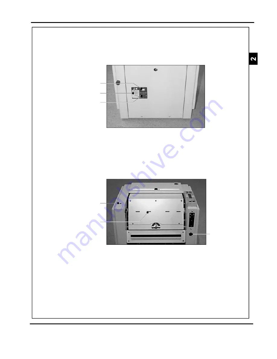
SYSTEM
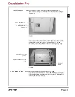
Mains Input
Mains ON/OFF Switch
Voltage Indicator Label
FIGURE 5
FIGURE 6
Conveyor
Socket
Status Indicator Light
(Yellow)
Staple Head Indicator Light
(Red)
SWITCHING ON
Plug in the BMP unit to a single phase power supply of
the correct voltage as indicated by the mains input (see
Figure 5).
Also ensure the outfeed conveyor cable is connected to
the socket on the BMP (see Figure 6). If the TMP is
installed, ensure that this too is connected (see p. 30).
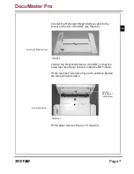
MOTORISED INFEED
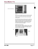
An optional Motorised Infeed (P/N 041-571) is
recommended. This fits on to the BMP infeed and makes
offline use easier. A paper tray (see Figure 7) is supplied
with the Motorised Infeed.
DocuMaster Pro
Summary of Contents for Documaster Pro
Page 11: ...Page 9 SYSTEM THIS PAGE IS INTENTIONALLY BLANK DocuMaster Pro ...
Page 15: ...Page 13 SYSTEM THIS PAGE IS INTENTIONALLY BLANK DocuMaster Pro ...
Page 19: ...Page 17 SYSTEM THIS PAGE IS INTENTIONALLY BLANK DocuMaster Pro ...
Page 23: ...Page 21 SYSTEM THIS PAGE IS INTENTIONALLY BLANK DocuMaster Pro ...
Page 27: ...Page 25 SYSTEM THIS PAGE IS INTENTIONALLY BLANK DocuMaster Pro ...
Page 31: ...Page 29 SYSTEM THIS PAGE IS INTENTIONALLY BLANK DocuMaster Pro ...
Page 35: ...Page 33 SYSTEM THIS PAGE IS INTENTIONALLY BLANK DocuMaster Pro ...
Page 45: ...Page 43 SYSTEM THIS PAGE IS INTENTIONALLY BLANK DocuMaster Pro ...
Page 47: ...Page 45 SYSTEM DocuMaster Pro ...


