31
OBSERVED
FAULT
POSSIBLE CAUSE
FAULT ISOLATION/REPAIR
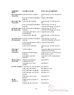
No machine
initialisation.
Power supply not connected.
Check voltage in power cord.
Main fuse F1 defective.
Check fuse at power receptacle.
Secondary fuses F2 and F3
defective.
Check fuses at transformer
1.
Transformer defective.
Check voltage at primary side of
transformer, according to label on
transformer. If OK go to step
2
.
Main switch SW1 defective.
Check function of main switch
SW1.
Interlock switch SW6 or SW14
defective.
Check function of Interlock switch
SW6 and SW14.
2.
Transformer defective.
Check voltage on secondary side
of transformer.
Rectifier/Capacitor defective.
Check voltage between Red and
Black for 36 V DC ± 10 %
P4 connector defective.
Check voltage between pin 4 and 5
for 14 V AC
P11 connector defective.
Check voltage between pin 1 and 2
for 36 V DC
Main circuit board PCB MD6DC
defective.
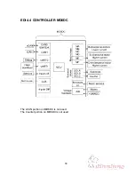
Check voltage according to EDI 4.3
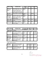
Infeed motor M6
inoperative.
Fuse F2 defective.
Check fuse F2 at transformer.
Main circuit board PCB MD6DC
defective.
Check for app. 24 V DC at
Connector J2 pin 3 and 10.
Interface cable/wire harness
defective.
Check for app. 30 V DC at
connector J1 on Addon PCB
between pin 1 and 2.
Infeed motor M6 defective.
Check for app. 24 V DC at motor
M6.
Stapler motor M1
inoperative.
Fuse F2 defective.
Check fuse F2 at transformer.
Main circuit board PCB MD6DC
defective.
Check for app. 24 V DC at
Connector J3 pin 6 and 7.
Staple mode switch SW2 on
front panel defective.
Check function of SW2.
Stapler motor M1 defective.
Check for app. 24 V DC at motor
M6.
5. FAULT ISOLATION PROCEDURE (FIP)
FIP 5.1 FAULT ISOLATION PROCEDURE
Summary of Contents for Plockmatic BM 60
Page 2: ...BOOKLET MAKER BM 60 61 SERVICE MANUAL 3 October 2006 Part no 60243 ...
Page 3: ......
Page 27: ...26 ...
Page 36: ......
Page 37: ......


