༁໙บʰʕʍʒɁႱࢠ
LUBRICATING UNIT ALARMS
198
8
ឬ֖
8
WARNING
ൡಽໃɥȪɖȪȹȢȳȨȗǿ
Turn OFF the main power.
ᴹਖ਼ᬲᴻ
<Procedure>
1)
࿁ՠʃʛʔɥΈȶȹʴʴ˂ʟʚʵʠɥʧʽʡటͶȞɜɝ
۶Ȭǿ
1)
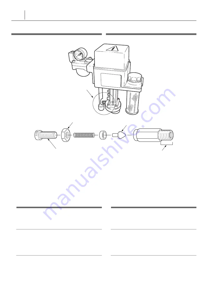
Detach the relief valve from the pump using a single-ended
wrench.
2)
ʷʍɹʔʍʒɥɔȹᝩɀȫɥɝ۶Ȭǿ
2)
Loosen the lock nut and remove the adjusting screw.
3)
ґᜓȪȲʴʴ˂ʟʚʵʠɥɲɬʠʷ˂ɗཌྷบȽȼȺ๎Ȭ
ɞǿ
3)
Clean the disassembled relief valve with compressed air
and kerosene.
7
า
7
CAUTION
٢᎔ሳɥΈႊȬɞکնɂǾᄻȾȲȗሥ࿎ȽȼȟоɜȽȗ
ɛșί឴ʫɶʗɥᅔႊȪȹȢȳȨȗᴥʫɶʗᅔႊᐐɥֆ
ɓᴦǿ
When using compressed air, wear protective glasses to
prevent eye damage from dust or foreign matter (those
who wear glasses are included).
2
าᜤ
2
NOTE
ɾʩɁئᣅɒȽȼȾɛɝǾʚʵʠʐ˂ʛȾϾȟȕɞکնɂ̬૰
ȪȹȢȳȨȗǿ
Take care to check for dust contamination of the tapered section. If
scratches are visible on the tapered section of the relief valve,
replacement is necessary.
4)
ґᜓȻᣡɁਖ਼ᬲȺጸɒȹɞǿ
4)
Perform the above procedure in reverse to reassemble.
2
าᜤ
2
NOTE
ʁ˂ʵɁᆍ࿁ȽȼȟюȾоɜȽȗɛșȾาȪȹȢȳȨȗǿ
Ensure that foreign matter such as flakes from the sealing material
does not enter the tapered section during reassembly.
5)
ᥓከюɁɲɬȠɥᚐșǿ
5)
Bleed air from the piping.
1
ᥓከюɁɲɬȠȾȷȗȹɂ
1
Refer to “Lubricating Unit Air Removal” (page 197) for
details on bleeding air from the piping.
6)
ʴʴ˂ʟʚʵʠɁᝩɥᚐșǿ
6)
Adjust the relief valve.
Relief Valve
ʴʴ˂ʟʚʵʠ
Lock Nut
Adjusting Screw
Relief Valve Disassembly
Valve
Tapered Threaded Section
ʷʍɹʔʍʒ
ᝩɀȫ
ʴʴᴪʟʚʵʠґᜓَ
ʚʵʠ
ʐ˂ʛɀȫ
Summary of Contents for NL1500/500
Page 8: ......
Page 9: ...CONTENTS FOR SAFE MACHINE OPERATION REGULAR MAINTENANCE TROUBLESHOOTING INDEX...
Page 10: ......
Page 19: ...FOR SAFE MACHINE OPERATION...
Page 50: ......
Page 51: ...1 1 CHAPTER 1 CHAPTER 1 REGULAR MAINTENANCE...
Page 167: ...2 2 CHAPTER 2 CHAPTER 2 TROUBLESHOOTING...
Page 181: ...181 ZERO POINT RETURN COMMAND ALARM TRIGGERED X X Axis Z Z Axis Y Y Axis...
Page 232: ......
Page 240: ......
Page 242: ......


