PREPARATION BEFORE STARTING MASS PRODUCTION E-19
1.
When using the NC functions, refer to page A-23 (5-6) to find the details of them.
2.
Depending on workpiece shapes and machine specifications, there may be cases
that the work coordinate system is shifted in the X-axis direction. There may also be
cases that no-load running of a program is executed after removing a workpiece
from the chuck instead of entering the work coordinate system shift data.
3.
When checking the program by shifting the coordinate system in the Z-axis direction,
input a negative value for the shift amount on the spindle 1 side, and input a positive
value for the shift amount on the spindle 2 side.
4.
Correct the program after program check if necessary.
5.
After finishing the program check, always reset the shift amount to its original value.
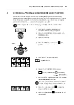
The procedure to check the program by shifting the coordinate system 100 mm in the Z-axis
direction is explained below:
1)
Carry out the procedure explained in 4-1
"Preparations for Checking a Program".
2)
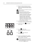
Place the DOOR INTERLOCK key-switch in the
NORMAL
position.
3)
Close the front door.
4)
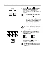
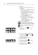
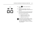
Place the PANEL key-switch in the
(ON)
position.
5)
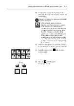
Press the head selection switch
(head 1) or
(head 2) to select the required turret.
6)
Carry out the zero return operation.
7)
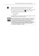
Display the WORK COORDINATES screen.
8)
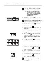
Set the Z-axis shift amount 100 mm for "Z" in the
"EXT" column.
Input "
−
100.0" using the data entry keys.
1.
To input the Z-axis shift amount for spindle
2, press the following keys in order (S type):
NOTE
ON
PANEL
/EDIT
OFF
PANEL
1
2
MEM
MDI
TAPE
EDIT
H
JOG
RPD
ZRN
NOTE
0
0
0
1
.


