OPERATION PANELS A-7
4
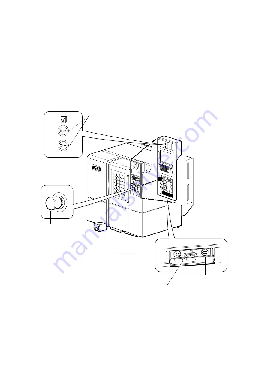
SWITCHES FOR POWER SUPPLY
The arrangement of the switches related to the power supply, and their functions, are described
here.
4-1
Arrangement of Power Supply Switches
The numbers indicate the subsections where explanations of switches are given.
Machine Front
4-2-4 "Emergency Stop Button
[EMERGENCY STOP]"
4-2-5 "RS232C Interface Connector at the
Lower Area of the Operation Panel"
Lower side of the operation panel
4-2-6 "100 VAC Service Outlet (Option)"
NC operation panel
Operation panel


