SETTING OF COORDINATE SYSTEM D-1
1
COORDINATE SYSTEM
Programs are created based on the coordinate system with the origin (X0, Z0) as the machining
zero point.
Therefore, to control tool movement as programmed, it is necessary to inform the NC the physical
tool position in the coordinate system at the start of the program.
Usually, the start point is the position that the turret reaches at the zero return position (machine
zero point).
This is indicated in the program in the following manner:
1.
G00 T_ ;
The coordinate system is set using the tool geometry offset function.
2.
G54; - G59;
The coordinate system is set using the work coordinate system setting G codes (G54 to
G59).
This is a brief explanation of a coordinate system.
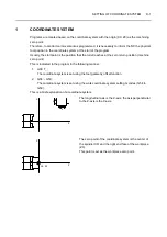
The longitudinal axis is the Z-axis; the axis perpendicular
to the Z-axis is the X-axis.
The zero point of the coordinate system is the center of
the spindle (X0) and the right end face of the workpiece
(Z0).
This point is set as the workpiece zero point.
X
Z
X
Z
X0, Z0
X
Z


