ZX Fire Alarm Control Panels
MORLEY-IAS
Installation Manual
Document No. 996-174-000-1, Revision: 01
Page 31
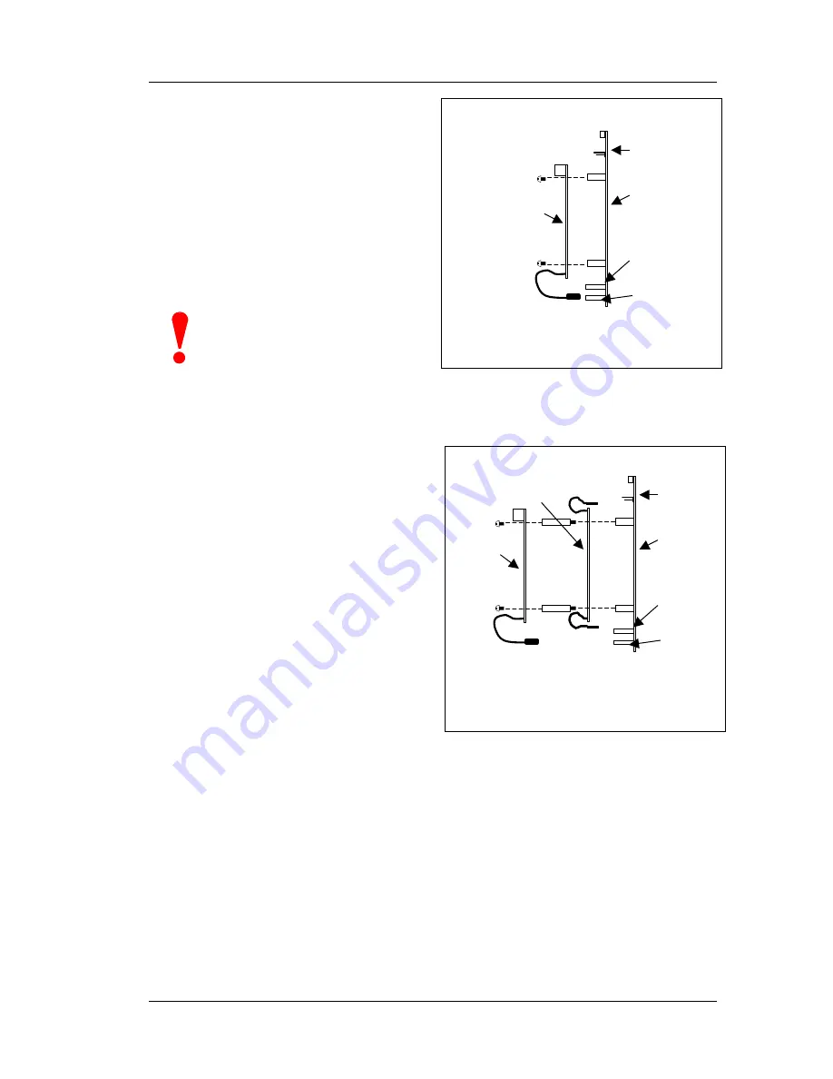
3.5.3.1
Mounting the Card Directly to the
Base Card
Use either the four fixing screws (M3 x
6mm) or the four nylon spacers (M3 x
30mm), supplied with the module, to
mount the card onto the nylon spacers
on the base card.
Plug the 8-way ribbon cable connector
into the 8-way socket (S-PORT-C and S-
PORT-D on ZX1Se/ZX2Se, PL2, PL3,
PL4 on ZX5Se) on the base card.
Ensure the connector is fully inserted
and that there is no misalignment.
Ensure that the 8-way ribbon
cable connector IS NOT inserted
into the 10-way connector on the
ZX5Se base card.
3.5.3.2
Mounting the Card Above the Loop Driver Module
The three serial interfaces may require to
be installed on top of the loop driver
boards (loops 3 – 5) in the ZX5Se or
ZX10Se panel.
Use the four nylon spacers (M3 x 30mm),
supplied with the RS485 module, to
mount the loop driver card to the base
card.
Use the four fixing screws (M3 x 6mm),
supplied with the module, to mount the
RS485 card onto the nylon spacers on
the loop driver card.
Plug the 10-way and 4-way ribbon cable
connectors of the loop driver card into the
appropriate sockets on the base card.
Plug the 8-way ribbon cable connector
from the interface card into the 8-way
socket (PL2, PL3, or PL4) on the base
card. Ensure the connector is fully
inserted and that there is no
misalignment.
Figure 31 – Mounting the RS485 / RS232
Module
Figure 32 – Mounting the RS485 / RS232
Module
Base Card
TOP
RS485/232
Interface Module
10-way
connector
4-way
connector
8-way
connector
Base Card
TOP
RS485/232
Interface
Module
10-way
connector
4-way
connector
8-way
connector
Loop
Driver
Module
Summary of Contents for FW9003 Range
Page 55: ......


