ZX Fire Alarm Control Panels
Page 34
Document No. 996-174-000-1, Revision: 01
Installation Manual
Quiescent
Condition
Alarm
Condition
A B
Item
Qty
Each Unit
Total (A)
(Units x Qty)
Each Unit
Total (A)
(Units x
Qty)
ZX5Se Panel
1
0.250
0.250
0.490
0.490
RS485 Module (EXP-004)
0.059
0.059
RS485 Module (EXP-004B)
0.025
0.025
RS232 Module (EXP-005)
0.059
0.059
Zone LED Expander (EXP-069-020 0r
EXP-069-060)
0.014
0.019
Loop Driver Modules
Morley-IAS (795-072-100)
0.012
0.012
System Sensor (795-068-100)
0.012
0.012
Apollo (795-066-100)
0.012
0.012
Hochiki (795-058-105)
0.021
0.021
Nittan (795-044-001)
0.035
0.035
Peripheral Units
(Maximum 0.340 Amps total auxiliary 24V
DC supply)
(Maximum 0.340 Amps total auxiliary
24V DC supply)
4
4
ZXR5B (Active)
0.125
2
0.150
3
ZXR4B (Passive)
0.125
2
0.150
3
4-Way Relay (EXP-014)
0.080
2
0.160
3
8-Way Input (EXP-029)
0.065
2
0.097
2
4-way sounder (EXP-015)
0.120
2
3.220
3
40-way Event / Mimic LED (EXP-065)
0.030
2
0.277
3
Hi485 (EXP-038) or (EXP-038B)
0.040
2
0.100
2
1
Sensor Current
Sounder A Load
Sounder B Load
Sounder C Load
Sounder D Load
Other devices connected to the system but not listed above.
Total A
Total B
Standby Period
Total A x 24 =
Alarm Period
Total B x 0.5 =
Total C
Total D
Battery Ah ( C + D ) x 1.25 =
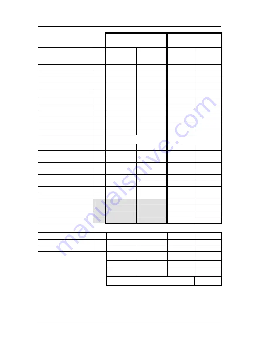
Table 8 - Current Rating Chart - ZX5Se
1:
Refer to Section – 4.1 below.
2:
Typical Quiescent currents quoted. Refer to data sheet for supply current range in all conditions.
3:
Maximum Alarm Load quoted. Refer to data sheet for supply current range in all conditions.
4:
Ensure total load of peripherals under all alarm and operating or fault conditions does not exceed maximum rating quoted.
Summary of Contents for FW9003 Range
Page 55: ......


