background image

ProStar Operator’s Manual

75

6.0

Troubleshooting

74

Problem: 

The ProStar is not charging the battery.

Solution: 

Check the three (3) battery SOC LEDs.  If they are 

flashing in a sequence, see Section 5.2 - LED Fault 

Indications - of this manual to determine the cause.  

A metered model, an RM-1 meter, or MSView PC      

software will display active faults and alarms.
If the LED indications are normal, check the fuses,        

breakers, and wiring connections in the power source 

wiring.  With a multi-meter, check the array voltage 

directly at the ProStar solar input terminals.  Input 

voltage must be greater than battery voltage before 

charging will begin.

Problem:

Controller makes buzzing and humming noises.

Solution:

No action is required.  This is expected due to      

magnetic resonance and circuit switching.

If troubleshooting does not correct the problem, 
please refer to Morningstar’s Warranty Claim           
Procedure in Section 6.


WARRANTY


LIMITED WARRANTY - Morningstar Solar Controllers 

and Inverters


All Morningstar 

Professional Series

TM

 products, except the 

SureSine

TM

 inverter, are warrantied to be free from defects 

in materials and workmanship for a period of FIVE (5) years 
from the date of shipment to the original end user. Warranty 
on replaced units, or field-replaced components, will be 
limited only to the duration of the original product coverage. 
Morningstar 

Essentials Series

TM

,

 and SureSine

TM

 inverter, 

products are warrantied to be free from defects in materials 
and workmanship for a period of TWO (2) years from the 
date of shipment to the original end user. Warranty on 
replaced units, or field-replaced components, will be limited 
only to the duration of the original product coverage. 
Morningstar will, at its option, repair or replace any such 
defective units. 

WARRANTY EXCLUSIONS AND LIMITATIONS


This warranty does not apply under the following conditions: 
• Damage by accident, negligence, abuse or improper use 
• PV or load currents exceeding the ratings of the product
• Unauthorized product modification or attempted repair 
• Damage occurring during shipment 
• Damage results from acts of nature such as lightning and 
weather extremes 
THE WARRANTY AND REMEDIES SET FORTH ABOVE 
ARE EXCLUSIVE AND IN LIEU OF ALL OTHERS, 
EXPRESS OR IMPLIED. MORNINGSTAR SPECIFICALLY 
DISCLAIMS ANY AND ALL IMPLIED WARRANTIES, 

6.0 WARRANTY AND POLICIES

Summary of Contents for Professional ProStar PS-15M

Page 1: ...ng System Controller Installation Operation and Maintenance Manual www morningstarcorp com ProStar TM MODELS PS 15 PS 30 PS 15M PS 30M For the most recent manual revision see the version at www morningstarcorp com ...

Page 2: ...1 Battery Charging Information 41 4 2 Load Control Information 54 4 3 LED Indications 56 4 3 1 Power up 56 4 3 2 Status LED 56 4 3 3 State of charge LEDs 57 4 4 Push button Use in Non Metered Versions 58 4 5 Custom Settings 59 4 5 1 Programming with Meter Display 59 4 5 2 Programming in MSView 61 Continued SPECIFICATION SUMMARY PS 15 PS 15M PS 30 PS 30M Nominal Battery voltage 12 or 24V 12 or 24V ...

Page 3: ...Appendix C Certifications 85 SAVE THESE INSTRUCTIONS This manual contains important safety installation operating and maintenance instructions for the ProStar solar controller The following symbols are used throughout this manual to indicate potentially dangerous conditions or mark important safety instructions WARNING Indicates a potentially dangerous condition Use extreme caution when performing...

Page 4: ...LLANCE LA BAT TERIE POURRAIT DEVENIR TROP CHARGÉE TEST ENTRE TOUTES LES BORNES ET LA MASSE AVANT DE TOUCHER AVERTISSEMENT LE PORT DE COMMUNICATION EST CONSIDÉRÉE COMME DVC B UN ISOLATEUR EXTERNE N EST NÉCES SAIRE SI C EST D ÊTRE CONNECTÉ À des consignes importantes de sécurité AVERTISSEMENT Indique une condition potentiellement dangereuse Faites preuve d une prudence extrême lors de la réalisation...

Page 5: ...elements and do not allow water to enter the controller Install the ProStar in a location that prevents casual contact The ProStar heatsink can become very hot during operation Use insulated tools when working with batteries Avoid wearing jewelry during installation The battery bank must be comprised of batteries of same type make and age UL IEC 62109 certified for use in negative ground or floati...

Page 6: ...et la pénétration d eau dans le contrôleur Installez le MPPT ProStar dans un endroit qui empêche le contact occasionnel Le dissipateur de chaleur ProStar peut devenir très chaud pendant le fonctionnement Utilisez des outils isolés pour travailler avec les batteries Évitez le port de bijoux pendant l installation Le groupe de batteries doit être constitué de batteries du même type fabricant et âge ...

Page 7: ... batteries is required Do not dispose of batteries in fire Refer to local regulations or codes for requirements AVERTISSEMENT Risque d Explosion Au rebut des piles est nécessaire Ne pas jeter les piles dans le feu Se référer aux réglementations locales ou des codes pour les exigences CAUTION When replacing batteries use properly specified number sizes types and ratings based on application and sys...

Page 8: ...rolyte level is correct before starting charging Do not attempt to charge a frozen battery Recycle the battery when it is replaced Entretien des batteries devrait être effectué ou su pervisé par un personnel bien informé sur les piles et les précautions de sécurité appropriées Soyez très prudent quand vous travaillez avec des grandes batteries au plomb Portez des lunettes de protection et ayez de ...

Page 9: ...e est remplacée 2 1 Overview Thank you for choosing the ProStar solar charge controller The ProStar battery charging process has been optimized for long battery life and improved system performance Self diagnostics and electronic error protections prevent damage when installation mistakes or system faults occur The controller also features eight 8 adjustable settings switches a communication port ...

Page 10: ...r a Class B digital device pursuant to Part 15 of the FCC rules These limits are designed to provide reasonable protection against harmful interference in a residential installation This equipment generates uses and can radiate radio frequency energy and if not installed and used in accordance with the instruction manual may cause harmful interference to radio communication However there is no gua...

Page 11: ...Meter Display optional Digital LCD monitoring and programming display 4 Battery Status Fault LED Indicators Three state of charge SOC LED indicators show charging status and controller faults 5 Solar Positive and Negative Terminals Power connections for Solar and cable terminations 6 Battery Positive and Negative Terminals Power connections for Battery and cable terminations 7 Load Positive and Ne...

Page 12: ...will automatically use the RTS for battery temperature compensation when installed The stan dard cable length is 33 ft 10m and can be extended to 100 ft 30m if required Installation instructions are provided with the RTS NOTE The use of a Remote Temperature Sensor RTS is strongly recommended Controller location air flow and system power can drastically affect the local temperature sensor reading A...

Page 13: ...n programming 3 0 INSTALLATION INSTRUCTIONS 3 1 General Installation Notes Read through the entire installation section first before beginning installation Do not install in locations where water can enter the controller Loose power connections and or corroded wires may result in resistive connections that melt wire insulation burn surrounding materials or even cause fire Ensure tight connections ...

Page 14: ...nd 50 Amps for the ProStar 30 M AVERTISSEMENT Fusibles solaires et de batterie ou CC des disjoncteurs sont néces saires dans le système Ces dispositifs de protection sont externes au contrôleur ProStar et doivent être au maximum de 20 A pour le ProStar 15 M et de 50 A pour le ProStar 30 M WARNING All breakers must be properly rated for wire ampacity which may require less than the maximum breaker ...

Page 15: ...ns are shown in table 3 1 below All voltage settings listed are for nominal 12 Volt batteries Multiply the voltage settings by two 2 for 24 Volt systems NOTE The charging profiles below are general guidelines for use at the operator s discretion Consult the battery manufacturer for optimal battery charge settings Battery Charging Set points 25 C multiply voltages by 2 for 24 Volt systems Switch 7 ...

Page 16: ...uded Tighten the mounting screws using care not to crack the plastic case Do not install directly over an easily combustible surface since the heat sink may get hot under certain operating conditions NOTE The heat sink must be in a vertical position fins up and down For proper air flow allow at least 15 cm 6 in of space above and below the controller and 50 mm 2 in at the sides see Figure 3 2 belo...

Page 17: ...tar must have its own solar array The load terminals of multiple controllers can only be wired together if the total load draw does not exceed the nameplate current of the LOWEST rated controller STEP 2 Battery Voltage Sense Wires WARNING Fire Hazard When connecting Battery Sense Wires install a 5 Amp fuse in the sense wire six inches from the battery terminal AVERTISSEMENT Risque d incendie Lors ...

Page 18: ...the sense wires will not compensate for losses in the power wires between the controller and the battery The battery sense wires are used to improve the accuracy of the battery charging The two sense wires can range in size from 1 0 to 0 25 mm2 16 to 24 AWG and should be cut to length as required to connect the battery to the voltage sense terminals A 2 position terminal see Figure 3 3 is used for...

Page 19: ...ery type how the system is used and other factors If the battery appears to be gasing too much or not charging enough the RTS can be added at any time after the system has been installed Connect the RTS to the 2 position terminal located to the left of the Load terminal see Figure 3 3 The RTS is supplied with 33 ft 10 m of 22 AWG 0 34 mm2 cable There is no polarity so either wire or can be connect...

Page 20: ... relier le négatif électrique du système CC à la borne de mise à la terre du contrôleur Si requis par le code ou la réglementation locale le négatif du système doit être relié à la terre en un seul point et via un GFPD STEP 5 Battery Connections at battery OR solar side but NOT both System Ground 6 in 150 mm Max Battery Battery 12V or 24V Battery Fuse or breaker sizing based on required wire ampac...

Page 21: ...ystème STEP 6 Solar Connections SOLAR SOLAR NOTE For design purposes array should be nominal 12V for 12V battery and nominal 24V for 24V battery Do not exceed 60Voc Solar Disconnect Fuse or breaker sizing based on required wire ampacity With the solar disconnect open connect the solar PV array wires to the ProStar solar terminals Use caution since the solar array will produce current whenever in s...

Page 22: ...ler s protections Watch the charging status and then the three battery state of charge SOC LEDs blink in sequence G Y R confirming proper start up If they do not light check the battery polarity and battery voltage The green yellow or red LED will light depending on the battery state of charge SOC Confirm that one of these LEDs is on before going to the next step Close solar disconnect If the sola...

Page 23: ...endant le chargement du ProStar To prevent damage power down must be done in the reverse order as power up 4 0 OPERATION 4 1 Battery Charging Information 4 Stage Charging The ProStar has a 4 stage battery charging algorithm for rapid efficient and safe battery charging Figure 4 1 below shows the sequence of stages NIGHT NIGHT BULK CHARGE ABSORPTION FLOAT EQUALIZE VOLTAGE TIME Figure 4 1 ProStar Ch...

Page 24: ...he ProStar reduces the battery voltage to the Float voltage set point When the battery is fully recharged there can be no more chemical reactions and all the charging current is turned into heat and gasing The float stage provides a very low rate of maintenance charging while reducing the heating and gasing of a fully charged battery The purpose of float is to protect the battery from long term ov...

Page 25: ... perte de matière active des plaques Une égalisation trop élevée ou trop longue peut être dommageable Passez en revue les conditions requises pour la batterie particulière utili sée dans votre système Certain battery types benefit from a periodic boost charge to stir the electrolyte level the cell Voltages and complete the chemical reactions Equalization EQ charging raises the battery voltage abov...

Page 26: ...alize The ideal frequency of equalizations depends on the battery type lead calcium lead antimony etc the depth of discharging battery age temperature and other factors One very broad guide is to equalize flooded batteries every one to three months or every five to ten deep discharges Some batteries such as the L 16 group will need more frequent equaliza tions The difference between the highest ce...

Page 27: ...ff 7 L 16 15 40 13 40 16 00 180 180 240 14 on on on 8 Custom Custom Custom Custom Custom Custom Custom Custom Sealed ba ery type includes gel and AGM ba eries Battery Charge Settings The ProStar provides seven 7 standard battery charging settings that are selected with the settings switches see Table 4 1 above These standard charging settings are suitable for lead acid batteries ranging from seale...

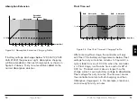
Page 28: ...0 4 00 5 00 6 00 Float V Bulk Float Absorption Absorption 60 mins below Float Voltage time hrs Bulk Figure 4 3 Float Exit Time out Charging Profile After entering Float stage the controller will only exit Float if the battery voltage remains below Float voltage for sixty cumulative minutes In figure 4 3 a system load turns on at 3 30 hrs when the controller is in Float stage runs for one hour and ...

Page 29: ... cycle Figure 4 4 above illustrates this concept At 0 00 hrs dawn battery voltage is below the Float Cancel threshold voltage The diagram shows where Float stage would have occurred if Float was not cancelled Equalize Time out 1 00 2 00 3 00 4 00 5 00 6 00 Absorp V Bulk Float Equalize Equalize timeout time hrs Equalize V Figure 4 5 Equalize time out charging profile The charging profile in figure ...

Page 30: ...sation Values LVD Warning As the battery discharges the Battery Status LEDs will transition from green to yellow and then from yellow to flashing red The flashing red indication is a warning that a low voltage disconnect event will occur soon The amount of time between a green SOC indication and load disconnect will depend on many factors including rate of discharge based on amount of load current...

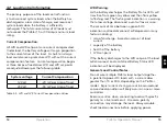
Page 31: ...ht The Status LED will flash red whenever an error condition s exists Table 4 4 below lists the Status LED indications Color Indication Operating State None Off with heartbeat Night Green On Solid with heartbeat Charging Red Flashing Error Red On Solid with heartbeat2 Critical Error 1 Heartbeat indication flickers the Status LED on briefly every 5 seconds 2 Heartbeat indication flickers the Status...

Page 32: ...DIP 7 setting press and hold the push button for 5 seconds to initiate an Equalization EQ Lighting Control Mode DIP 1 ON A quick press and release of the push button will clear any errors or reminders that are present A second quick press will then conduct a five minute lighting test If no errors or reminders are present the initial press will conduct the lighting test A lighting test is used to v...

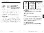
Page 33: ... No Firmware Version Battery Type Absorption Voltage Float Voltage EQ Voltage Input Mode System Voltage For metered models see the included complete meter map insert also available in the ProStar support documents at http www morningstarcorp com 4 5 2 Programming in MSView Beyond the preset DIP switch options the ProStar s charging profile and all other settings are customizable using MSView PC so...

Page 34: ...n programmed in MSView or using the meter with DIP 1 4 5 6 ON and the unit programmed custom timing will be in effect With DIP 1 OFF down all lighting control functions are disabled Using either MSView or the meter display four channels are available for setting timers that can work separately or in combination See Section 4 5 6 Lighting Programming Using the Meter Display for more details 4 5 6 L...

Page 35: ...ecommendations both timers settings match AND for either timers settings OR 4 5 7 Low Temperature Foldback The ProStar has a Low Temperature Foldback option which can be used to protect lithium batteries from being charged in cold conditions Custom settings defining the bounds of charge current reduction due to low battery temperature can be programmed in MSView or with the Advanced Custom Setting...

Page 36: ...perate at full rated current at the maximum rated ambient temperature This alarm indicates that there is insufficient airflow and that the heatsink temperature is approaching unsafe limits If the controller frequently reports this alarm condition corrective action must be taken to provide better air flow or to relocate the controller to a cooler spot RTS Open The Remote Temperature Sensor is not c...

Page 37: ...d current exceeds the maximum load current rating the ProStar will disconnect the load The greater the overload the faster the load will be disconnected A small overload could take a few minutes to disconnect The ProStar will attempt to reconnect the load two 2 times Each attempt is approximately ten 10 seconds apart If the overload remains after two 2 attempts the load will remain disconnected un...

Page 38: ...atus LED None Battery status LEDs R G sequencing This fault is set when battery voltage is above normal operating limits The controller will disconnect the load output and set a Load High Voltage Disconnect fault This fault is designed to protect sensitive loads from excessive voltage Recovery occurs at HVD re connect threshold if programmed and the fault will clear automatically High Heatsink Tem...

Page 39: ...rized Morningstar dealer for support Fault Charging Status LED Battery SOC LEDs PV FET Short Solid red R Y G sequencing Load FET Short Solid red R Y G sequencing Load FET Open Solid red R Y G sequencing Damaged local temperature sensor Solid red only if RTS is invalid R Y G sequencing Damaged heatsink temperature sensor Solid red R Y G sequencing Software Solid red R Y G sequencing Internal power ...

Page 40: ...arrantied to be free from defects in materials and workmanship for a period of FIVE 5 years from the date of shipment to the original end user Warranty on replaced units or field replaced components will be limited only to the duration of the original product coverage Morningstar Essentials SeriesTM and SureSineTM inverter products are warrantied to be free from defects in materials and workmanshi...

Page 41: ...described in Morningstar manuals and datasheets Please be advised The Morningstar Technical Support Group generally provides referrals for requested system consultations or design configuration sizing services Distributors dealers system designers installers and vast online resources including the String Calculator array design tool at www morningstarcorp com are available to assist in these areas...

Page 42: ...eplacement shipment has been received return of failed unit s is required before further warranty replacements can be considered for the original or future cases NOTE An RMA number must be issued by Morningstar prior to return of any unit s under this warranty Please do not return units without an RMA or case number Doing so will increase the time required to resolve your claim PS 15 PS 30 PS 15M ...

Page 43: ...D LVR Compensation threshold 3A Load and Solar Control multiply voltages by 2 for 24 Volt systems Default values customizable LVD1 11 5V LVR1 12 6V Instant LVD 10 0V HVD solar Highest set point in preset charging profile 0 5V 25ºC HVD load1 Disabled HVDR solar 13 8V 25ºC HVDR load1 Disabled LVD Warning 10 mins 1 Applies to units with Firmware v18 and higher LVD Override 10 mins Maximum LVD overrid...

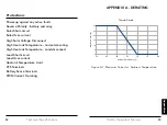
Page 44: ... Solar Voltage Disconnect High Heatsink Temperature Current de rating High Heatsink Temperature Load disconnect Load Short circuit Load Over current Heatsink Temperature Limit RTS Terminals Battery Sense Terminals PWM Current De rating 0 5 10 15 20 25 30 50 55 60 65 70 75 80 Maximum Current A AmbientTemperature C Thermal Derate Figure A 1 Maximum Current vs Ambient Temperature APPENDIX A DERATING ...

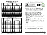
Page 45: ... 6 10 17 27 3 voltage drop Annealed copper wire at 20 C APPENDIX B Wire Sizing UL121201 CSA C22 2 213 Nonincendive Electrcal Equipment for Use in Class I Division 2 Hazardous Classified Locations Groups A B C D Temperature Group T5 EN 61000 6 2 2005 AC 2005 EMC Immunity EN 61000 6 4 2007 A1 2011 EMC Emissions Industry Canada CAN ICES 3 B NMB 3 B IEC 62109 1 2010 Safety of Power Converters in PV Sy...

Reviews: